
■ indicates standard specification (※ can be omitted)
Model Coding Examples:| ① | Type (See figures below) | |
|
Front USB | |
|
Rear USB / Waterproof gasket included on front | |
|
With display / With DIN rail mounting fixture * | |
|
Without display / With DIN rail mounting fixture * | |
| *No mounting hooks | ||
| ② | Number of CHs | |
|
1CH | |
| ③ | Input Signal | |
|
Resistance meter input | |
| ④ | Sensor Power Supply [Option] | |
|
None | |
|
+12V 60mA max | |
|
+5V 150mA max | |
|
Other xxV (Please contact us) | |
| Examples | ||
|
+24V | |
|
+3.3V | |
| *The terminal arrangement for the sensor power supply option varies depending on other installed options. If you require the sensor power supply option, please contact us in advance. | ||
| ⑤ | Option 1 | |
| Analog Output | ||
|
None | |
|
0-10V | |
|
0-5V | |
|
±10V | |
|
±5V | |
|
4-20mA | |
|
Alarm 1 point | |
|
No output options for both ⑤ and ⑥ | |
| ⑥ | Option 2 | |
| Digital Communication | ||
|
None | |
|
CAN | |
|
Modbus RTU (Under development) | |
|
RS-485 | |
|
Additional Control Input 2 points | |
|
Alarm 2 points | |
| Analog Output | ||
|
0-10V | |
|
0-5V | |
|
±10V | |
|
±5V | |
|
4-20mA | |
| If both Option 1 and Option 2 are analog outputs, please list them in alphabetical order. Example: YES -> E1I1 ("E" comes before "I") / NO -> I1E1 |
||
| ⑦ | Display Color | |
|
Red | |
| ⑧ | Terminal Block Shape | |
|
Spring-lock type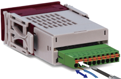 |
|
|
M2 Screw plug connector 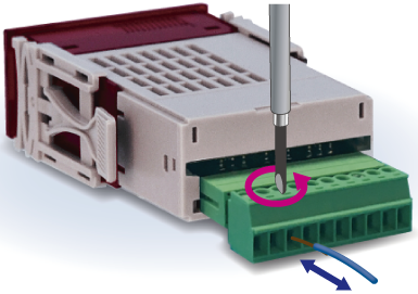 |
|
| [0] 2401 Type |
| Front USB |
 |
| [1] 2411 Type |
Rear USB / Front waterproof gasket included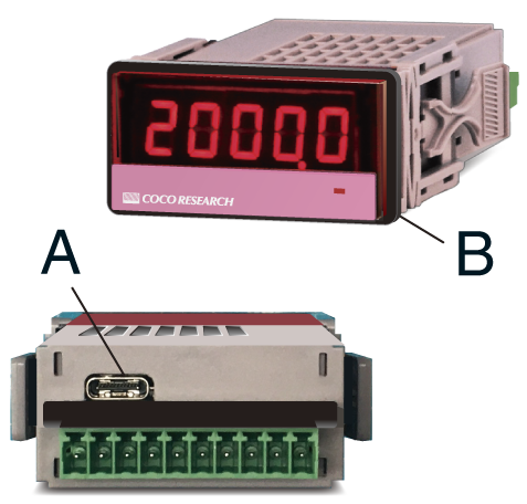 A: Rear USB Type-C connector B: Front waterproof gasket included |
| [3] 2431 Type |
With display / DIN rail mounting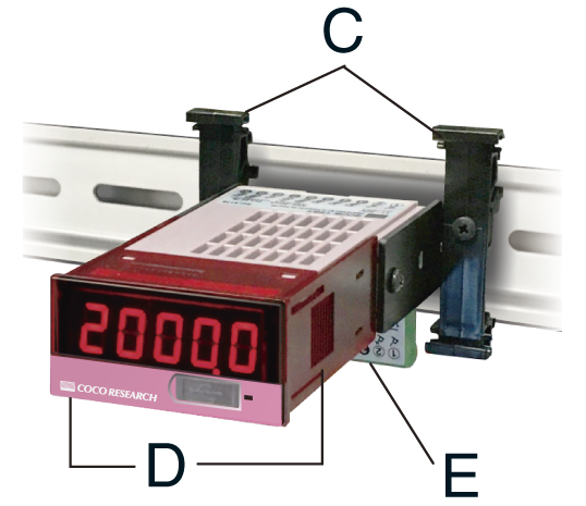 C: DIN rail mounting fixture C: DIN rail mounting fixtureD: Without mounting hooks E: Connector *DIN rail is not included |
| [5] 2451 Type |
Without display / DIN rail mounting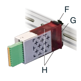 F: DIN rail mounting fixture F: DIN rail mounting fixtureG: Without display H: Without mounting hooks *DIN rail is not included |