Technical Info: Trigger Level and Hysteresis
When inputting a signal into a measuring instrument, if the trigger level does not have a certain range (width), the output may fluctuate (chatter) near the signal switching point.
If the input signal crosses back and forth across the trigger level due to noise, it may be misidentified as a valid pulse. (Figure 1)
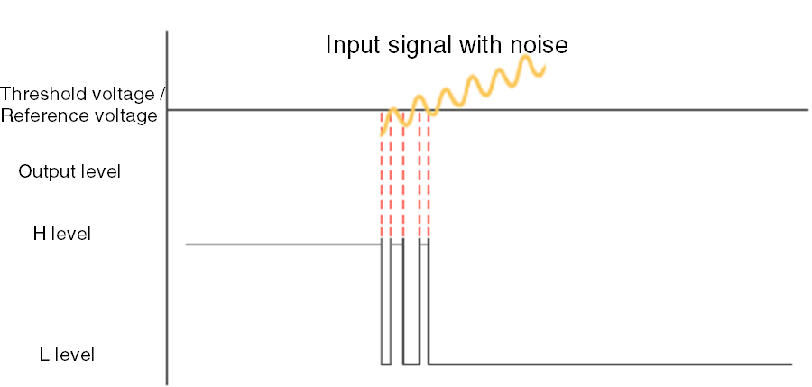 Fig.1 False count due to noise
To avoid this problem, many measuring instruments are designed so that the trigger level changes slightly once it is first exceeded. This ensures that even if the signal fluctuates slightly thereafter, it does not immediately fall back below the trigger level. (Figure 2)
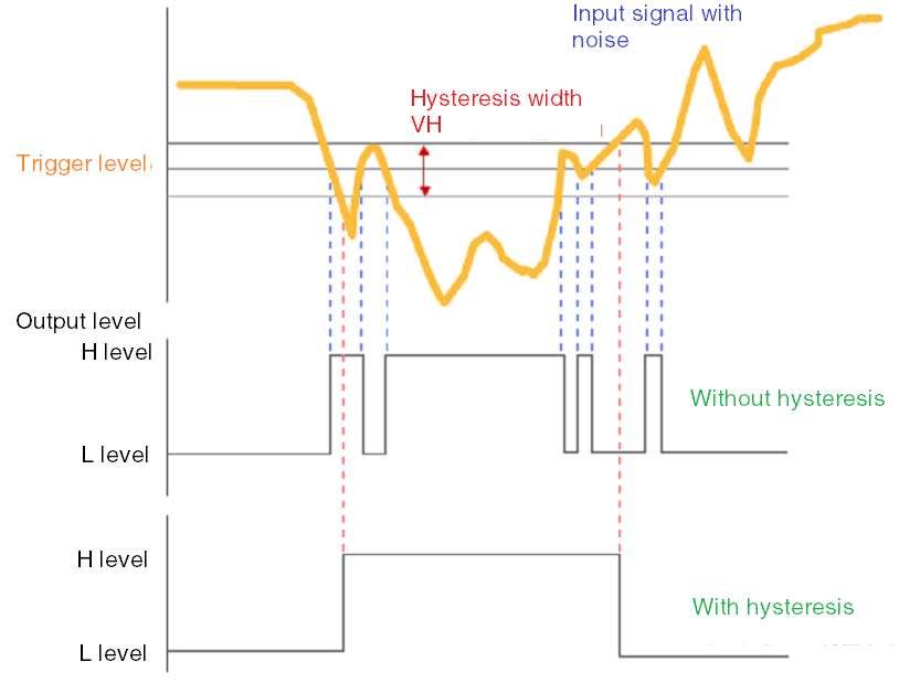 Fig.2 Output change depending on hysteresis characteristics
Because it follows different trigger levels for the rising and falling edges, this phenomenon is called hysteresis. The range by which the trigger level changes is called the hysteresis width.