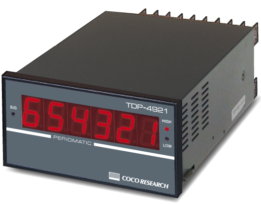
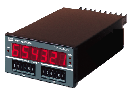
Pulse Counter [Totalizer] CNT-4921/4931 [Digital panel meter, Signal converter]
| 4 MHz with scaling function. For length, angle, displacement, and flow rate measurement, etc. |
- Input frequency up to 4 MHz, A/B phase pulse (up to 1 MHz possible), and directional signal input also supported.
- Reversible measurement without cumulative error - Various options including 16-bit analog output with 0.5 ms updates.
- This unit is a powerful tool for experiments and factory control lines.
Combinable sensors
 Gear Tooth Sensors
 Flow sensors
 Rotary encoders
 Linear encoders
Input frequency 0-4MHz (for single phase) 0-1MHz (for A/B phase)
No range switching required..
Supports a variety of input signals
In addition to single-phase signals such as open collector output, contact pulse, voltage pulse, and AC.
When 2-phase input is used, reverse measurement is also possible.
Compatible with various pulse output sensors such as magnetic gear speed sensors, power generation type electromagnetic pickups,
flow sensors, rotary encoders, photoelectric sensors, and linear scales.
Scaling
Totalized value per pulse and decimal point position of display can be set as desired.
2-phase 4-multiplication measurement
A/B-phase signals can be measured in quadruplicate.
2-channel non-contact output comparator provided as standard
External control
Direct control of preset, reset and hold.
Forward and reverse directions can be switched only by program setting,
no wiring replacement required
Wiring errors and changes in test conditions can be handled by simply changing settings.
Easy to install and set up / Prevent accidental operation
Setting buttons are located behind the front panel to prevent accidental operation.
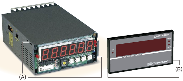
(A)Panel mounting mechanism: Easy installation from the front by one person
(B)Tool-free front panel: Easy installation by simply pressing the lower left and right sides
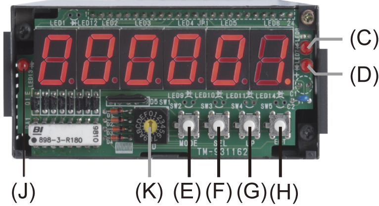 |
(C)HIGH comparator operation indicator (D)LOW comparator operation indicator (E)MODE button (F)Digit selection button (G)Numeric setting button (H)ENTER button (J)Input signal indicator (K)Individual ID setting switch when using multiple units (used only with RS-485 option) |
RS-232C interface
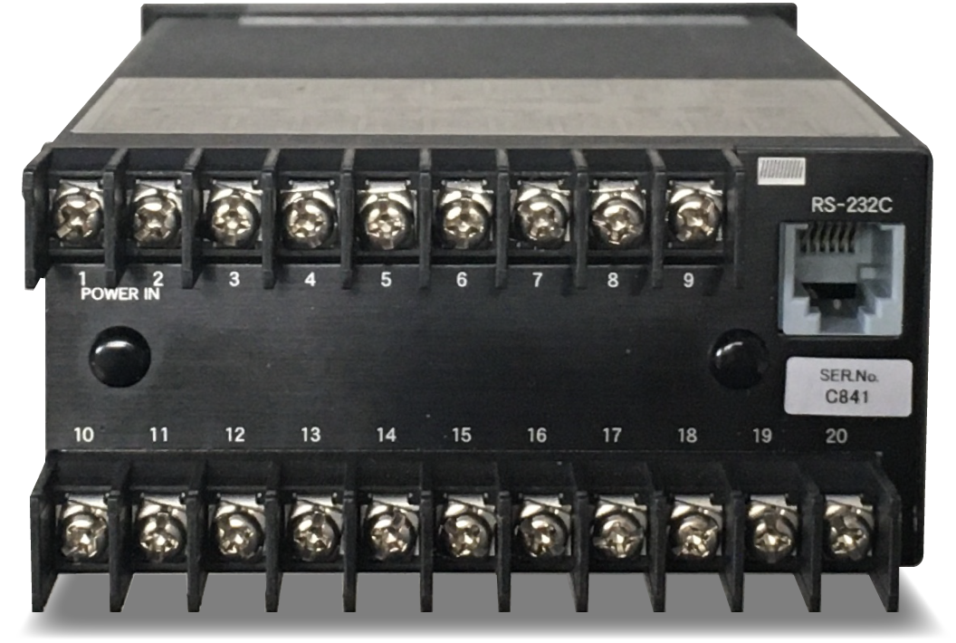 |
Only setting changes are possible. / Measurement data readout is not possible. Cable not included. Use optional RS-232C cable, etc. *The following RS-232C communication cable (sold separately) is required. CSS-M06D09 (9-pin D-SUB) or CSS-M06D25 (25-pin D-SUB), both approx. 2.5 m long *For RS-232C data continuous output, please contact us. << Rear side |
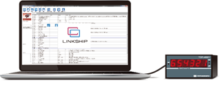
Software LINKSHIP for setting value management and report printing
RS-232C terminal on the rear of the main unit is connected to a PC with a communication cable (CSS-M06, etc.) for setting.
| Main Functions [For setting data only] - Reading data from this unit - Writing data to this unit - Saving data to PC - Collation of multiple setting data - Display of instruction manuals *[Supported OS] Windows7 / 8 /10 (32bit/64bit version) |
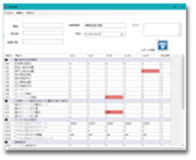 Collation and printing of set value lists |
 |
High-speed, high-precision Analog output:
16-bit resolution, 0.5ms output update time
Select from 4 types of output: 0-10V, 1(0)-5V, ±10V, and 4(0)-20mA.
RS-485 communication
Internal setting values can be changed and measurement data can be retrieved.
BCD parallel output
Open collector output or TTL or CMOS output of 6-digit parallel signals with polarity.
Easy connection to sequencers, large display units, and digital printers.
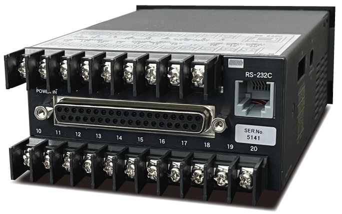 Rear view with BCD output option model
Expanded comparator output 2ch
Two additional channels can be added to the standard 2-channel comparator output.
Up to 4 channels of HIGH and LOW comparator outputs are possible.
Specifications
| Name Model |
Pulse Counter [Totalizer] CNT-4921 (Push switch type) CNT-4931 (Digi-switch type) |
|
| Input | Number of input points |
1 point |
| Logic input | ||
| Input level | [H] level 3.8V or more / [L] level 1V or less | |
| Single-phase pulse | Input frequency range Input pulse width Trigger direction Input indicator |
0 to 4MHz 100ns or more for both H and L levels Falling SIG (blinks at falling edge, lights continuously with high-speed pulse) |
| UP/DOWN signal (separate pulse) |
Input frequency range Input pulse width Trigger direction Input indicator |
0 to 4MHz 100ns or more for both H and L levels Falling SIG (blinks at falling UP/DOWN, lights continuously with high-speed pulse) |
| Phase A/B signal (90°phase difference, internal 4-multiplication count) |
Input frequency range Input pulse width Trigger direction Input indicator |
0 to 1MHz 60ns or more for both H and L levels Falling/rising SIG (blinks at falling phase A, lights continuously with high-speed pulse) |
| Direction signal | Input frequency range Input pulse width Trigger direction Input indicator |
0 to 4MHz 100ns or more for both H and L levels [Speed input] falling / [Direction input] falling/rising SIG (blinks at falling edge, lights continuously with high-speed pulse) |
| Zero cross input | ||
| Input sensitivity | 100 mV or more AC signal | |
Single-phase pulse |
Input frequency range Input pulse width Trigger direction Input indicator |
0 to 150 kHz 5μs or more for both H and L levels Falling SIG (blinks at falling edge, lights continuously with high-speed pulse) |
| Input Circuit | A (UP) signal input function Pull-up ON / OFF (Pull-up to +5V with approx. 6kΩ / Pull-down to GND with 10kΩ) Logic/zero cross switching LPF circuit 150kHz(-3dB,-6dB/oct)/1.5kHz(-3dB,-6dB/oct) B signal input function Pull-up ON / OFF (Pulled up to +5V with approx. 6kΩ / Pulled down to GND with 10kΩ) Logic signal only DOWN signal input Pull-up always ON (Pulled up to +5V with 5kΩ) Logic signal only |
|
| Input withstand voltage | ±30V | |
| Input connector | Terminal block 7.62mm pitch M3 free terminal screw | |
| Power supply for sensor | [Standard] CNT-49x1 +12V±10% 150mA max / [Option] CNT-49x1-L +5V±10% 200mA max | |
| Calculation | Display rate Maximum pulse input Setting value memory |
Set display value for 1 pulse, 0.000000001 to 99999999 *Set in program mode ±2 47 - 1 (±47Bit) Internal counting stops above maximum pulse. Not related to display count Non-volatile memory |
| Display | Scaling function Indicator (Numerical Display) Display color Number of digits Display range Polarity indication Over indication Zero indication Decimal point position Display update time Indicator |
Set the displayed value per pulse with 6 digits and decimal point position. *Set in program mode Segment LED Character height 14.2mm [CNT-49x1] Red LED / [CNT-49x1-G] Green LED 6 digits -19999999 to 999999 - (-) on/+ (-) off Up to ±19999999, double illumination indicates over digits. Leading zero suppress Semi-fixed (Decimal point position is set in pull-gram mode) 0 : □□□□□□. ~ 5 : □ . . □□□□□ 20ms 3 round LEDs SIG: Pulse input indicator (blinks when pulse input, lights continuously with high-speed pulse) HIGH: Lit when HIGH comparator output is ON LOW: Lights when LOW comparator output is ON |
| External control input |
Control input Input signal Input circuit Input withstand voltage Function Input connector |
Input from rear terminal (short-circuited to GND terminal)
Input at L level width of 2 ms or more Logic signal +5V pull-up at approx. 5kΩ +30V/-25V [Hold] Display, analog output, BCD data, and RS-485 data stop updating Internal count and comparator operation continues [Reset] Count value is reset to zero [Preset] Count value is set to the internally set value Terminal block 7.62mm pitch M3 free terminal screw |
| Comparator output |
Setting method Number of outputs Number of setting digits Polarity setting Decimal point position Output signal Rated ON resistance Output logic Response time Output connector |
[CNT-4921] Setting in program mode / [CNT-4931] By setting the digi-switch on the front panel
2 points (HIGH, LOW) HIGH 6 digits LOW 6 digits 0 = +, 1 = - (set in program mode) Same as display position Isolated non-contact output (photo-MOS relay) 350V DC, 80mA max. (resistive load) / 240V AC, 80mA max. (resistive load) 50Ω max. Comparison with polarity (0 is greater than minus), ON at or above / below *set in program mode 3ms (max) Terminal block 7.62mm pitch M3 free terminal screw |
| RS-232C communication *Please contact us for RS-232C data continuous output. |
Communication method Communication level Communication parameter Communication code Connector |
Asynchronous
RS-232C [Baud rate] 2400bps fixed, [Start bit] 1 bit, [Stop bit] 1bit, [Data length] 8 bits, [Parity bit] None ASCII, [Character] 0 to 9, LF, CR 6-pole modular jack |
| General information |
Backup function Power input Power consumption Dimensions Weight Ambient operating atmosphere Ambient operating temp. / humid. Storage temperature range |
Totalized count values are stored in nonvolatile memory.
[CNT-49x1-AF] 100-240V AC (max. rated 80-264V AC) 50/60Hz / [CNT-49x1-DF] 9.6-30V DC [AC power model] 8VA or less / [DC power model] 6VA or less H48 x W96 x D150 DIN standard Approx. 700g No corrosive gas 0 °C to +40 °C / 85%HR or less (no condensation) -20°C to +70°C |
| Analog output option |
Output Item Output signal, Resolution Output update time Output rate Load resistance Output accuracy Temperature coefficient Linearity Output connector |
Totalizer output
[CNT-49x1-E] 0 to 10 V approx. 57000 [CNT-49x1-H] 1 to 5 V approx. 45000 / 0 to 5 V approx. 57000 [CNT-49x1-R] ±10V approx. 57000 [CNT-49x1-I] 4 to 20 mA approx. 45000 / 0 to 20 mA Approx. 57000 0.5 ms (maximum delay from pulse input to analog output: 0.7 ms) Indicated value setting by arbitrary full scale * Set in program mode [Voltage output] 4.7kΩ or more / [Current output] 560Ω or less [Voltage output] ±0.05% or less of full scale @23°C / [Current output] ±0.2% or less of full scale @23°C ±200ppm/℃ max. ±0.1% max. Terminal block 7.62mm pitch M3 free terminal screw |
| BCD output option |
Signal form Data Update time Control signals Output connectore |
[CNT-49x1-P] Open collector output / [CNT-49x1-T] CMOS, TTL output
6 digits parallel signal with polarity 0.5ms or less Latch input / Output control input / BUSY output D-Sub 37P socket, fixture screw specification is M2.6 x 0.45 mm. |
| RS-485 communication option |
Optional model Number of connected units Communication format Communication method Communication standard Communication speed Communication parameter Communication code Internal data update speed Communication connector |
CNT-49x1-S
Max. 32 units Multidrop serial communication Asynchronous RS-485 9,600bps/19,200bps (set in program mode) [Start bit] 1 bit, [Stop bit] 1 bit, [Data length] 8 bits, [Parity bit] None ASCII 1ms or less Terminal block 7.62mm pitch M3 free terminal screw |
| Extended comparator output option |
Option model Setting method Number of outputs Number of setting digits Polarity setting Decimal point position Output signal Rated ON resistance Output logic Response time Output connector |
CNT-49x1-C
Set in program mode 2 points (COMP1, COMP2) [COMP1] 6 digits / [COMP2] 6 digits 0 = +, 1 = - (set in program mode) Same as display position Isolated non-contact output (photo-MOS relay) 350V DC, 80mA max. (resistive load) / 240V AC, 80mA max. (resistive load) 50Ω max. Comparison with polarity (0 is greater than minus) ON at or above / below (set in program mode) 3ms (max) Terminal block 7.62mm pitch M3 free terminal screw |
| Speed/Totalizer [Switchable] SPD-4801 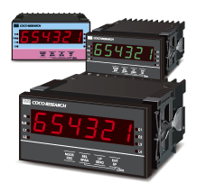 |
- For frequency meter, tachometer, flowmeter, speed meter, totalizer, counter applications - 48x96 DIN size - Input 0.6mHz-1MHz, optional A/B phase and line driver - Simultaneous 16-bit analog output and CAN output - Analog output (0.1ms update)/Alarm output (option) - CAN (1ms update)/RS-485 communication (option) - Setting and measurement operations can be performed with buttons on the front panel. - Equipped with USB Type-C connector: logging and setting - Zero shift/span shift/accumulation stop/start - Trigger level, hysteresis, pull-up, low-pass filter - Compatible with Coco Research's measurement management software LINKSHIP (free of charge) |
> Counters / Totalizers list
> Flow sensors list
> Gear tooth sensors list
