|
Dual Analog Outputs & Ethernet (LAN) options now available |
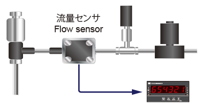
Measures frequency via sensor pulse signals. Displays and outputs at any rate such as rpm, L/h, km/h, etc.
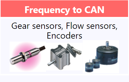
| Input Pulse (Frequency) Output Sensors |
||
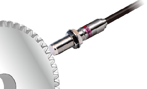
Gear Sensor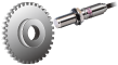 |
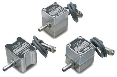
Flow Sensor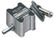 |
|
Rotary Encoder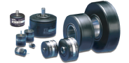 |
Linear Encoder |
 |
Input Pulse • 5V Logic • Zero Cross • 12V Logic |
||
| Sensor Power Supply • 12V / 5V / Others |
 |
|
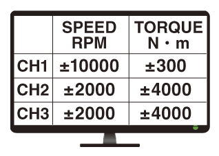
| Processing (Speed, Freq, Period, Totalizing) | ||||||||||
|
||||||||||
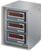
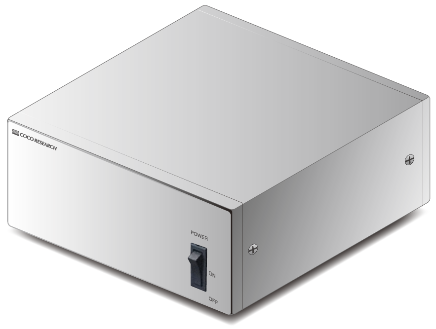
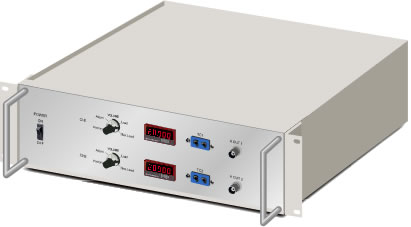
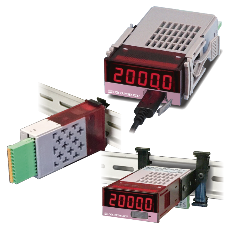
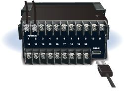
SPD-4801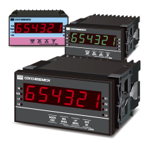 |
|
|||||||||
| Power • DC 9.6-30V • AC 100-240V |
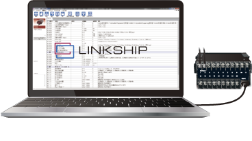
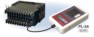
Setup • Front Buttons • LINKSHIP (Software) • PL-5A (External Unit) |
|||||||||
| Output | |||||||
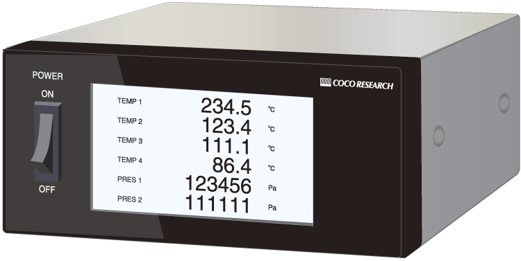
PC, PLC, Logger, Oscilloscope, etc.  
   |
|||||||
| > View Case Studies |
| Flexible Measurement & Ch Customization |
| Available from Single Unit Orders |
| Convenient, Simple & Cost-effective |
| System-integrated Calibration |
| Modifications: Power Supply, Outputs, Comms |
| Calibration & Traceability Certs Available |
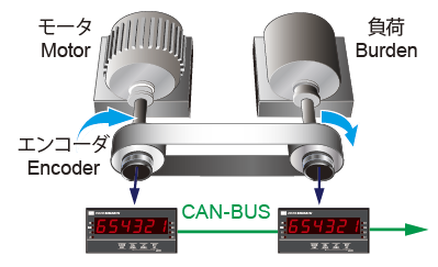
Significantly reduces wiring compared to BCD via 3-wire connection.
Strong noise immunity and safety via robust error detection.
| SAE J1939 (DLC 8-byte or less) customization cases available Please consult us for other customizations. |
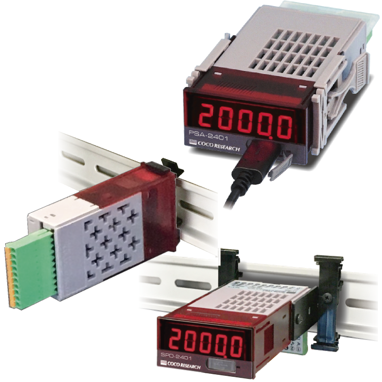
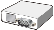
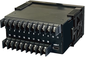
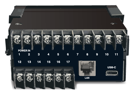
RS-485, Ethernet (LAN) [NEW] [Option]
USB Type-C 1ms Update [Standard] For Logging & Setup
Resolution > 50,000, full/zero scale settings, zero-adjustment supported.
Dual Analog Output available [NEW] [Option]Optional dual outputs, e.g., concurrent 0-10V and 4-20mA.
Alarm Output 1ms Update [Option] 1-4 points
| 5V Logic |
| Zero Cross |
| NPN Open Collector |
| 12V Logic |
| Custom Signals |
| Isolated Input |
| A/B Phase Input |
| Line Driver |
| Trigger 0-9.99V |
| 3-step Hysteresis |
| Pull-up ON/OFF |
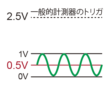
Standard meters often fix at 2.5V, but SPD supports 0-9V adjustable in 10mV increments.
Highly compatible with various sensors.
 |
or | 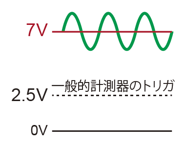 |
can be input |
| Threshold 0.5V | Threshold 7V |
| 5V |
| 12V |
| Other Voltages |
| What is PeriomaticTM? |
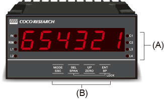
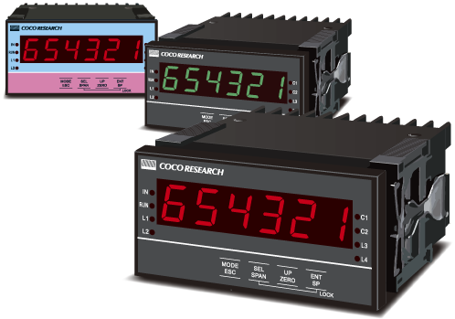
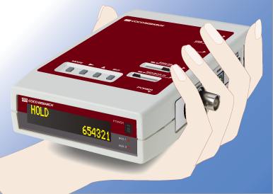
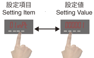
(A) Operation Indicator LED
(B) Front Panel Sheet Buttons
- [Program Mode] MODE, Digit selection, Value setting, ENTER
- [Measurement Mode] Span shift, Zero shift
- Key lock, etc.
| > To LINKSHIP Page |
 |
|
 |
|
| Model | SPD-4801 | |||||||||||||||
| Measurement Method | PeriomaticTM B-Method (Period Calculation) | |||||||||||||||
| Input Section | ||||||||||||||||
| Input Points | 1 point | |||||||||||||||
| Input Range | 0.0006Hz - 1.0MHz | |||||||||||||||
| Input Resolution | Approx. 10.4ns (96MHz) | |||||||||||||||
| Input Signal | 5V Logic, Zero-cross, NPN Open Collector, 12V Logic, Customized Signal | |||||||||||||||
| Input Method | Single-phase, 2-phase (Direction, UP/DOWN) | |||||||||||||||
| General-purpose Input Type | ||||||||||||||||
| Level/Sensitivity |
|
|||||||||||||||
| Input Pulse | ≥0.2μs (S/M Hysteresis) / ≥0.3μs (L Hysteresis) for both H/L levels | |||||||||||||||
| Input Resistance | 10kΩ: 5V Logic, Zero-cross, NPN, Customized (Trigger ≤4.7V) 5kΩ: 12V Logic, Customized (Trigger ≥4.71V) |
|||||||||||||||
| Withstand Voltage | ±30V *General-purpose input option: I/O is non-isolated |
|||||||||||||||
| Line Driver Input Type (Option) | ||||||||||||||||
| Input Signal | Line Driver Signal | |||||||||||||||
| Withstand Voltage | ±25V (Differential) | |||||||||||||||
| Recommended Driver | AM26LS31 equivalent | |||||||||||||||
| Termination | 300Ω (Standard) *Line driver input option: I/O is isolated |
|||||||||||||||
| 2-phase (AB phase) Input Type (Option) Switchable between single and 2-phase. For single-phase, levels follow 2-phase specs. | ||||||||||||||||
| Level/Sensitivity |
|
|||||||||||||||
| Input Pulse | ≥0.2μs for both H/L levels | |||||||||||||||
| Input Resistance | 10kΩ | |||||||||||||||
| Withstand Voltage | ±30V | |||||||||||||||
| Common Input Features | ||||||||||||||||
| Low-pass Filter | OFF / 500Hz / 5kHz / 120kHz / 800kHz | |||||||||||||||
| Trigger | Falling edge | |||||||||||||||
| Connector | 7.62mm pitch terminal block, M3 screws | |||||||||||||||
| Sensor Power Output | Option: [H] DC +12V±5% 60mA max / [L] DC +5V±5% 150mA max | |||||||||||||||
| Calculation Section | ||||||||||||||||
| Measurement Mode | Speedometer / Frequency Meter / Period Meter (seconds only) / Totalizer [Switchable] | |||||||||||||||
| Calculation Rate | Set ref. pulses, ref. change amount, and speed unit time relative to input freq. | |||||||||||||||
| Division Ratio | 1 - 60000 | |||||||||||||||
| Moving Average | 1 - 99 | |||||||||||||||
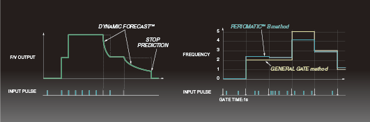
| Dynamic PredictionTM | 8 levels (incl. continuous/stop prediction) | |||||||||||||||
| Control Input | None or 1 point (model dependent). [D2] option adds 2 points. | |||||||||||||||
| (Settings) | Functions set per control input (CTL) for external control [Functions] Hold (Current/Max/Min/Peak-to-Peak), Zero-shift (Total), Span-shift (Total), Stop/Start totalization [Logic] Normally Open / Normally Closed |
|||||||||||||||
| (Operation) | CTL terminal reflects settings when shorted (or opened) to GND based on logic | |||||||||||||||
| (Data Comm.) | Command control via comms (USB, CAN, RS-485) *Comms commands cannot be cleared via terminals; reset required | |||||||||||||||
| Low-cut Function | Judges stop at speeds below the set value | |||||||||||||||
| Display Section | ||||||||||||||||
| Display (Numeric) | 6-digit 7-segment LED, 14.2mm height. SPD-4801: Red / SPD-4801-G: Green (Option) Range: -199999 to 999999. Polarity: "-" lights for reverse rotation Overflow: OL. Zero Display: Leading zero suppression Update: 0.3s (Settable 0.1 - 9.9s). Accuracy: 20ppm±1digit |
|||||||||||||||
| Decimal Point | Semi-fixed (set in program mode): 0 to 4 digits | |||||||||||||||
| Indicators (4 Circular LEDs) |
[IN] Input activity. [RUN] Function setting active. [COMP1][COMP2] Comparator output ON (Option) |
|||||||||||||||
| USB Communication | ||||||||||||||||
| Specs | USB 2.0 (Serial port comms via Virtual COM, 230.4kbps) | |||||||||||||||
| Functions | Read/Write settings, continuous output of measured values | |||||||||||||||
| Output Update | 1ms - 9999.9ms (0.1ms increments) | |||||||||||||||
| General Specifications | ||||||||||||||||
| Operating Environment | -10°C to +50°C, 35-85%RH (Non-condensing) | |||||||||||||||
| Supply Voltage [Select Model] |
[AF] AC100-240V (Max rating AC85-264V) 50/60Hz [DF] DC 9.6-30V (Max rating DC9-36V) with reverse protection |
|||||||||||||||
| Power Consumption | ≤3W | |||||||||||||||
| Isolation | Power supply vs. other I/O | |||||||||||||||
| Withstand Voltage | DC 500V for 1 minute between terminals | |||||||||||||||
| Weight | Approx. 340g | |||||||||||||||
| CAN Option | ||||||||||||||||
| Specs | CAN 2.0B 10k-1M bps. Format (Intel/Motorola), Frame (11-bit/29-bit) | |||||||||||||||
| Functions | Read/Write settings, continuous output of measured values | |||||||||||||||
| Setting Items | CAN TX ID, CAN RX ID | |||||||||||||||
| Output Update | 1ms - 9999.9ms (0.1ms increments) | |||||||||||||||
| RS-485 Option Modbus RTU support available upon request | ||||||||||||||||
| Max Connections | 32 units | |||||||||||||||
| Comm. Form | 2-wire multi-drop serial | |||||||||||||||
| Comm. Method | Asynchronous | |||||||||||||||
| Standard | RS-485 | |||||||||||||||
| Baud Rate | 9600 / 19200 / 38400 bps | |||||||||||||||
| Data Format | Start 1-bit / Stop 1-bit / Data 8-bit / Parity None | |||||||||||||||
| Code | ASCII | |||||||||||||||
| Functions | Read/Write settings, measurement output (responds to commands) | |||||||||||||||
| Analog Output Option | ||||||||||||||||
| Signal | [E1] 0-10V [E5] 0-5V [R1] ±10V [R5] ±5V [I1] 4-20mA [Select Model] | |||||||||||||||
| D/A Method | DAC method | |||||||||||||||
| Resolution | 16-bit (over 50,000) | |||||||||||||||
| Load Resistance | Voltage: ≥4.7kΩ / Current: ≤300Ω | |||||||||||||||
| Accuracy | ±0.1% of FS @ 23°C (Voltage and Current) | |||||||||||||||
| Temperature Drift | ≤±200ppm/°C | |||||||||||||||
| Scaling | Arbitrary scaling via full-scale and zero-scale settings | |||||||||||||||
| Update Time | 0.1ms - 9999.9ms (0.1ms increments) | |||||||||||||||
| I/O Delay | Update time + Analog rise time ≤ 150μs | |||||||||||||||
| Comparator (Alarm) Output Option | ||||||||||||||||
| Setting Method | Configured in program mode | |||||||||||||||
| Outputs | 0 - 4 points (depending on model selection) 1 point for line driver input with comparator analog output |
|||||||||||||||
| Output Type | Isolated contactless output (PhotoMOS relay), non-polarized ON resistance COMP-COM: [C2] ≤ 50Ω / [C1] ≤ 100Ω |
|||||||||||||||
| Load Voltage | Peak AC/DC 280V 100mA (Resistive), ON resistance ≤ 50Ω | |||||||||||||||
| Output Logic | Polarized comparison (0 > negative)
|
|||||||||||||||
| Update Time | Based on analog update setting / Response ≤ 1ms | |||||||||||||||
| Ethernet Option | ||||||||||||||||
| Connector | RJ-45 (Lantronix XPort) | |||||||||||||||
| Interface | 100BASE-TX / 10BASE-T (Auto-negotiation) Cat. 4 / Cat. 5 supported |
|||||||||||||||
| Specs | Protocol TCP/IP via Telnet connection | |||||||||||||||
| Update Time | Follows USB specs (1 - 9999ms) | |||||||||||||||
| Compatibility | DIX Ethernet Ver. 2.0 IEEE 802.3 | |||||||||||||||
| LED Display | 100BASE-TX / 10BASE-T | |||||||||||||||
| Link/Activity | Full/Half duplex (Telnet does not support SSL/TLS or SSH encrypted networks) | |||||||||||||||
- CAN Output
- 16-bit Analog (Voltage/Current) Output
- USB-C: Configuration & Data Logging
- Alarm Output / RS-485
- Configuration Management Software (Free): Report Printing & Data Logging
- Dual Analog Outputs [EX48]
- Ethernet (LAN) [EX48]