COCORESEARCH - Measurement Instrument Manufacturer
Products
Applications
Technical Info
Support
Company
Careers
Contact
ENGLISH
TOP OF
PAGE

Technical Info: Types of Pulse Signals

Voltage-Free Signals (Dry Contact)

Signals that only turn a switch ON/OFF without generating output voltage on their own.
To use them as pulse signals, current is measured by applying voltage to the circuit.
Signal sources include contact switches and open collector transistors shown below.

Contact Signal (Dry Contact)

Signal sources using electrical contacts include reed switches, relays, and mercury switches, as well as FET-based dry signal sources (Right diagram).
Circuit diagram of contact signal

Open Collector Signal

Using a transistor with an open collector instead of a mechanical contact provides a similar function to electrical contact switches.
PNP and NPN types differ in current flow direction (Right diagrams).

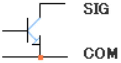
NPN Open Collector Signal

Circuit diagram of NPN open collector signal

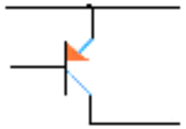
PNP Open Collector Signal

Circuit diagram of PNP open collector signal

Solid-State Relay (SSR)

Voltage Pulse Signals

Logic Signals

Logic IC

Capable of sourcing and sinking current. The typical voltage level is 5V.
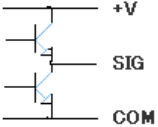
Totem-Pole
Output Circuit

Totem-pole output circuit diagram

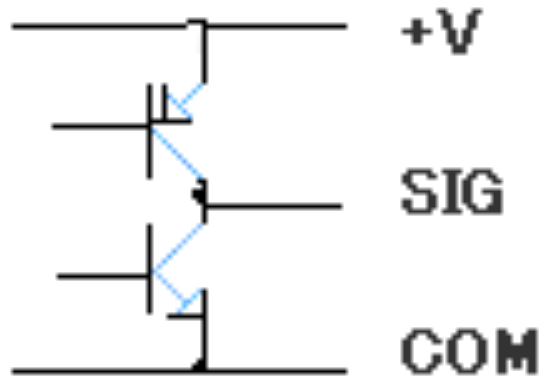
Complementary
Output Circuit

Complementary output circuit diagram
Example of unbalanced output circuit

Line Driver Output Signal

A balanced signal (also called differential or balanced signal) used to eliminate transmission noise effects by outputting logic signals of opposite polarities.
Requires a balanced input circuit on the receiver side. Operates stably over relatively long distances.

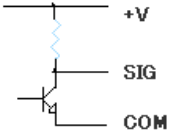
NPN Transistor Voltage Output

Similar to open collector outputs, but includes an output circuit where voltage is applied via a resistor.
Also called a pull-up output because the collector voltage is pulled up to the positive rail with a resistor.

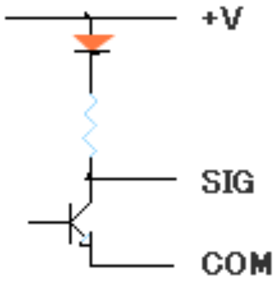
Semi-Open Collector Signal

A highly practical open collector signal that combines the advantages of both voltage-free and voltage pulse signals without interference from the receiving side voltage. Originally developed by COCORESEARCH.

Zero-Crossing Signal

Signals that cross the reference potential of 0V into positive and negative ranges. Includes various AC waveforms such as AC tachogenerators, sine-wave encoders, and self-generating electromagnetic flowmeters.

Circuit diagram of zero-crossing signal output

Related Information

Convert frequency pulses to voltage signalsF/V Converters
Mighty2 handy type tip type

Details >

Measure speed & flow rate with pulse signalsTachometers / Flow Counters
48x96 type 24x48 type handy type

Details >

Measure torque & mixing ratios with pulsesTorque & Analog Converters
HS-TAC 48x96 type 24x48 type

Details >

Convert rotation into frequency pulsesGear Sensors
Gear

Details >

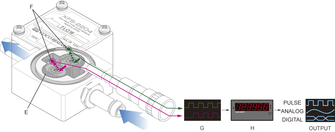
Convert flow rate into frequency pulsesFlow Sensors
system

Details >

Applications using this technology

Speed & Speed Ratio
speed

Details >

Angle, Position & Totalizing
angle

Details >

Flow Rate
flow rate

Details >

Torque & Mixing Ratio
torque

Details >

Rotational Measurement via Gear
gear

Details >

Related Articles | Pulse Measurement Technology

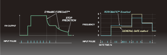
Original Frequency Measurement Tech: What is PeriomaticTM?
perio image
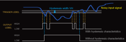
Trigger Level & Hysteresis
trigger image
Glossary [Rotation, Speed Measurement & Pulse Edition]
word image
> Inquiry Form