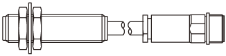
A magnetic rotation sensor consisting of a Hall element, magnet, and signal processing circuit.
It converts magnetic changes caused by the rotation of magnetic target gears into electrical signals and outputs them as logic signals.
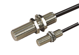
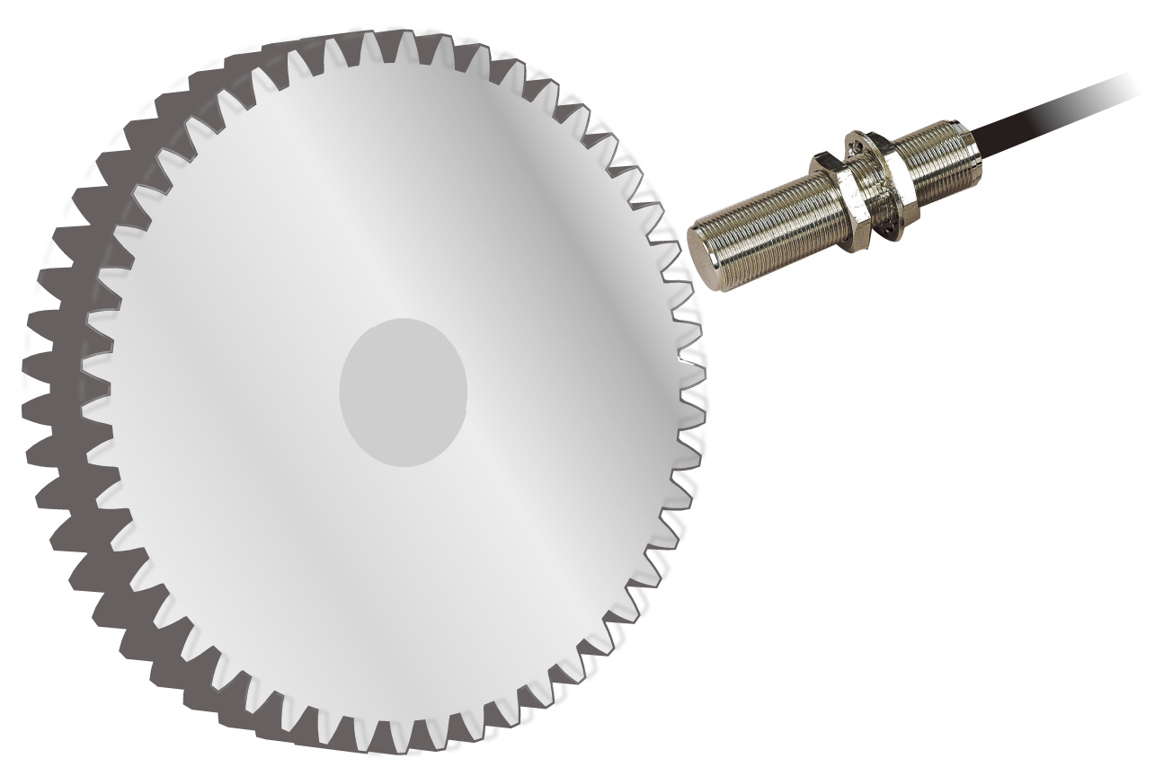
No rotation adjustment required
A unique output method combining the advantages of both open-collector and pull-up. Outputs pulses at a voltage close to the supply power
Threaded over the entire length for high mounting flexibility
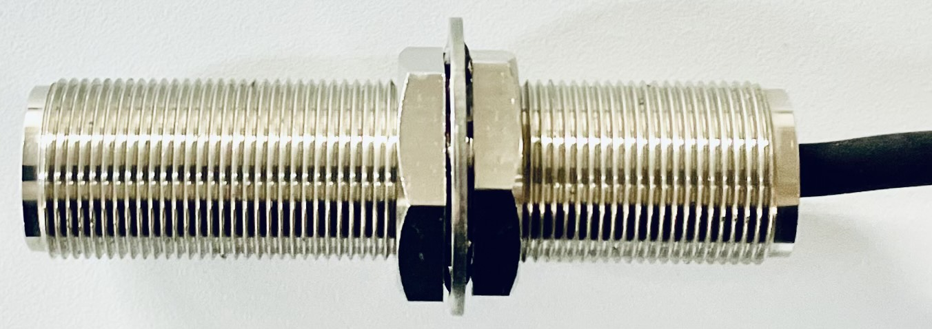
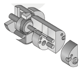
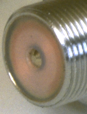
Sensing face features a completely sealed integrated metal case for high reliability
 |
 |
 |
| Conventional(Our model GP-2) | FDP Series | |
| Tip has a cap | Sealed integrated metal case: Blocks harmful liquids/gases |
|
| *Image is for illustration purposes |
Cables feature our proprietary extraction technology, Conical PressTM, to withstand water and oil exposure
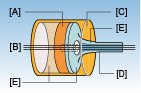
*Conceptual diagram of Conical Press
Direct Cable Out
High reliability without connectors
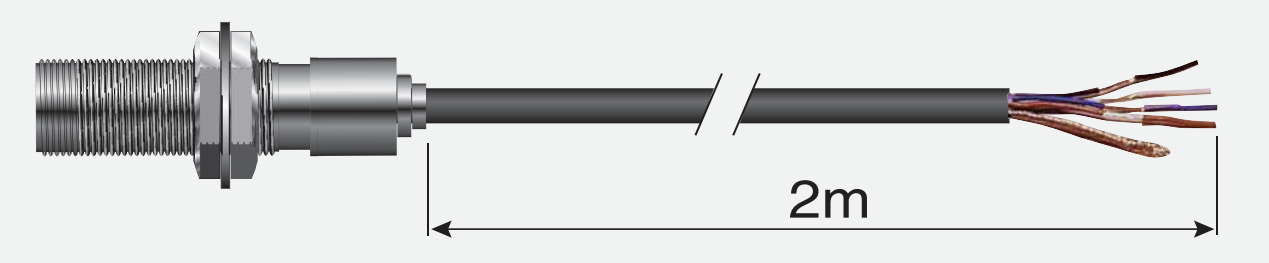
Detects any magnetic material with peaks and valleys
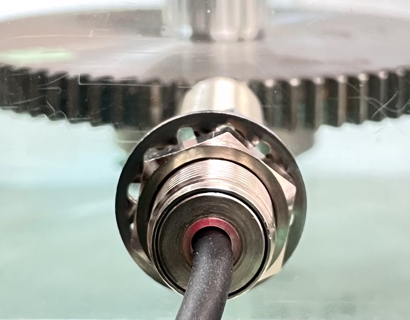
Converting Speed to CAN
| Learn More > |
| Speed → CAN |
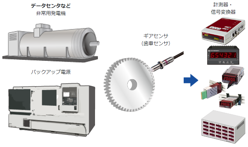
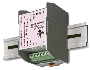
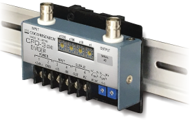
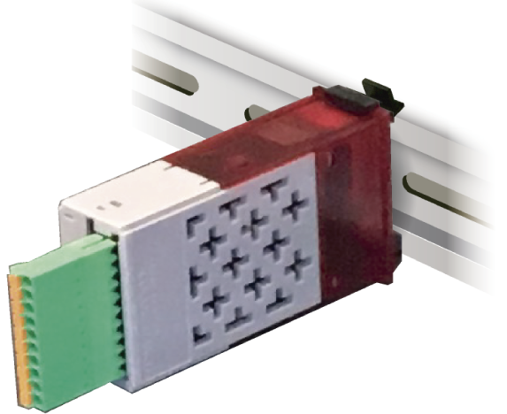
Using gear sensors with instruments/signal converters
|
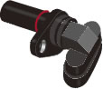
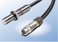
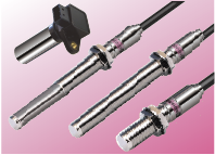
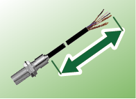
| Model Name | Magnetic Gear Speed Sensor | |
| Model No. | FDP10-A37 FDP10-A37-J6M [With Connector] |
FDP16-A65 FDP16-A65-J6M [With Connector] |
| Dimensions | M10 L:37 mm [M=10, P= 1mm] | M16 L:65 mm [M=16, P= 1mm] |
| Weight | [FDP10-A37] 85g / [FDP10-A37-J6M] 110g | [FDP16-A37] 150g / [FDP16-A37-J6M] 175g |
| Target Object | Material: Magnetic material (such as S45C carbon steel for machine structural use (JIS G 4051)), standard gear, and step height of 3 mm or more | |
| Compatible Module | M = 0.5 or greater | |
| Detection Distance | [Module 0.5] 0.1 - 0.4mm / [Module 1] 0.1 - 1.2mm / [Module 2] 0.1 - 2.6mm | |
| Detection Method | Single Hall element type | |
| Response Frequency Range | 0 - 15kHz | |
| Output Mode | High level upon proximity | |
| Output Circuit | Semi-open collector (open collector + pull-up) | |
| Output Voltage | Outputs at power supply voltage | |
| Output Current | 30mA max. (sink current) | |
| Power Supply Voltage | 4.5 - 25VDC, Ripple 10% max. | |
| Current Consumption | 30mA max. | |
| Operating Temperature Range | -20 - +70℃ | |
| Insulation Resistance | 50MΩ or more (Between shorted cables and case at DC500V megger) | |
| Dielectric Strength | AC500V 50/60Hz 1min between shorted cables and case | |
| Vibration Resistance | JIS C 0040 [Frequency range 10 - 55Hz, double amplitude 1.5mm, sweep time 5 min, sweep cycles: 20 times for each X, Y, Z direction, 60 times in total] | |
| Shock Resistance | JIS C 0044 [Drop floor: concrete, drop height: 1m, 2 times each] | |
| Magnet Polarity | Tip: S-pole | |
| Case Material | Brass (nickel-plated) | |
| Cable | 2m PVC 3-core shielded cable, core wire 0.2sq | |
| Operation Monitor LED |
Lights up upon proximity | |
| Accessories | 2 nuts, 1 toothed lock washer. | |
| Degree of Protection | IP67 | |
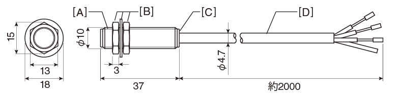
Brown +V
Black SIG OUT
Blue 0V
Shield: Insulated from main body
[A] M10 P=1 thread
[B] Included nut and toothed lock washer
[C] Operation check LED
[D] Shielded 3-core cable

a SIG OUT
b N.C.
c +V
d Shield
e 0V
f 0V
[E] R04-J6M connector circular 6P (male)*
[F] M14 P=1 thread
*Connector manufactured by Tajima Musen Denki Co., Ltd.
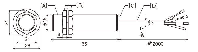
Brown +V
Black SIG OUT
Blue 0V
Shield: Insulated from main body
[A] M16 P=1 thread
[B] Included nut and toothed lock washer
[C] Operation check LED
[D] Shielded 3-core cable
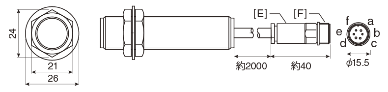
a SIG OUT
b N.C.
c +V
d Shield
e 0V
f 0V
[E] R04-J6M connector circular 6P (male)*
[F] M14 P=1 thread
*Connector manufactured by Tajima Musen Denki Co., Ltd.
|
| Extension Cable Model | Cable End | ||
| Cable Length 5m | Cable Length 10m | Cable Length 20m | |
| DK-005 | DK-010 | DK-020 | Y-type Crimp Terminal |
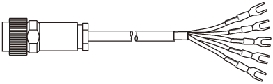 |
White SIG OUT Black N.C. Brown +V Blue 0V Shield |
||
| R04-P6F* 6-pin female | Y-type crimp terminal 1.25Y-3 | ||
| DK-005T | DK-010T | DK-020T | Plug Connector |
 |
a SIG OUT b N.C. c +V d Shield e 0V f N.C. |
||
| R04-P6F* 6-pin female | R03-P6M* 6-pin male | ||
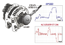
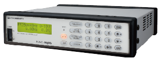
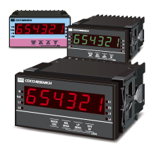
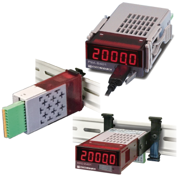
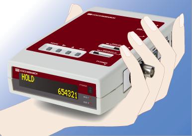
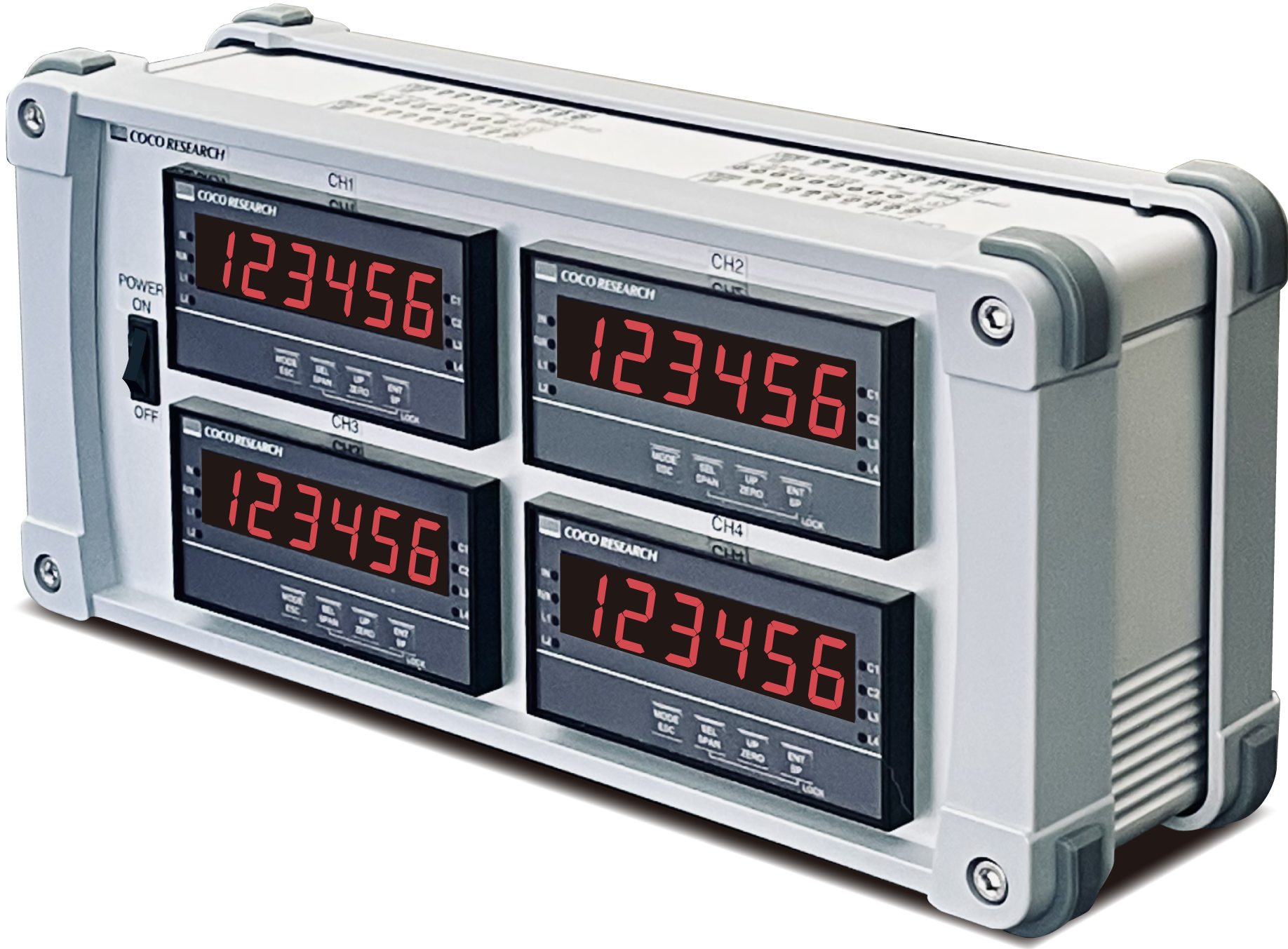
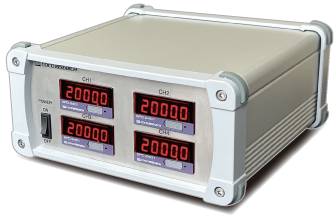
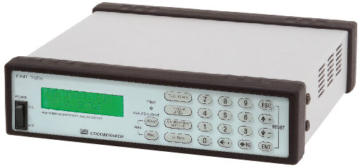
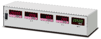
By combining gear sensors with our F/V converters, tachometers, high-speed pulse counters, etc., real-time measurement of rotational speed, angle, and more becomes possible, offering various advantages.
High Precision & High-Speed Response
Achieves high precision and high-speed response under all conditions, from stop, ultra-low speed to high speed, rapid acceleration, and rapid deceleration using the PeriomaticTM method F/V converters and tachometers.
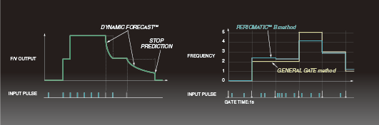
| > What is PeriomaticTM |
Improved Measurement Reliability and Safety
Peace of mind with equipment matching from a single manufacturer. Factory setting changes are also available (for measuring instruments).
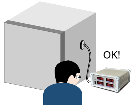
*Image for illustrative purposes
Capable of Supplying Power to Sensors*
Eliminates the need to prepare a separate power supply for sensors.
*Optional for certain models. GP series does not require a power supply.
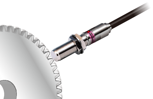 |
Sensor Power Supply   Measurement Signal |
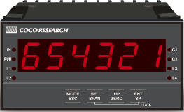 |
Enclosed Customized Products
|
| Technical Information: Types and Features of Pulse Signals > |
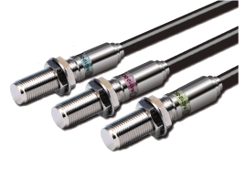 |
| > To Product Page |
Response 0 - 20kHz
Temperature -20 ~ +105℃
Power Supply DC4.5 - 25(17)V
Output Circuit
Semi-open collector*1
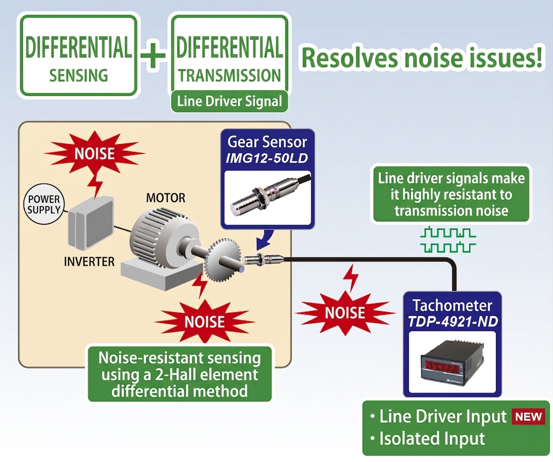
Line driver
Differential (balanced) CMOS logic*2
Detects from 0Hz, enabling accurate rotation measurement through jitter suppression technology
Line driver output type supports environments with long wiring
Equipped with a power supply reverse connection circuit to prevent failures caused by operational errors
 |
| > To Product Page |
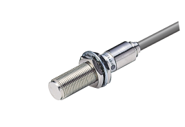
Response 0 - 15kHz
Temperature -20 ~ +80℃
Power Supply DC4.5 - 25V
Output Circuit
Semi-open collector*1
Pursuing ease of use as a general-purpose sensor
The output circuit is unbalanced, and an output voltage almost equivalent to the sensor power supply voltage can be obtained
Equipped with a semi-open collector output circuit so that it can be connected as-is even if the pull-up voltage at the signal receiving end is higher than the sensor output
 |
| > To Product Page |
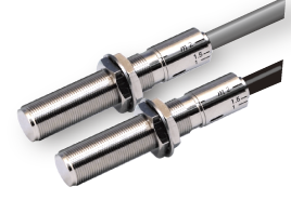
Response 10 - 30kHz
Temperature -40 ~ +150℃
Power Supply DC5 - 12V
Output Circuit
Open collector
Built-in amplifier, usable at high temperatures (150℃)
 |
| > To Product Page |
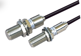
Response 0 - 15kHz
Temperature
-40 ~ +140℃ (RFP16A Power supply under 15V)
-40 ~ +126℃ (RFP16A Power supply 15V or more)
-20 ~ +80℃ (RFP16D)
Power Supply DC9 - 25V
Output Circuit
Semi-open collector*1
(A/B phase or Speed/Direction discrimination signal)
Detects both forward and reverse directions with a single unit. Reduces work such as hole machining and mounting adjustment
*Compatible with m1/1.5/2 / Involute gear verified
 |
| > To Product Page |
Response 220 - 50kHz
Temperature -20 ~ +100℃
Power Supply No power supply required
Output Circuit
Voltage output proportional to speed*3
0.5Vp-p or more
Self-generating type using a magnet and detection coil. No power supply required
Approaches gear tips, etc., and outputs a frequency signal proportional to the rotational speed
*1 Semi-open collector (open collector + pull-up): A proprietary output circuit developed by our company that allows connection as-is even if the pull-up voltage at the signal receiving end is higher than the sensor power supply voltage.
Unlike a simple open collector, pulse output with a voltage close to the sensor power supply voltage can be obtained.
*2 Differential (balanced) CMOS logic can be used as an unbalanced signal. When using as a balanced signal, please check the power supply voltage and output voltage specifications.
*3 The output voltage of the GP type is proportional to the speed in principle, but the GP type prevents unnecessary increases in output to improve reliability.