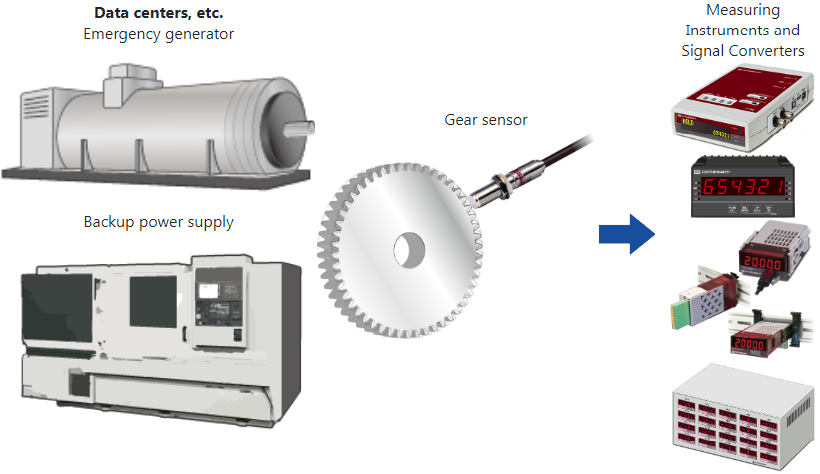
Detects both forward and reverse rotation with one sensor (compatible with gears m1/1.5/2, verified with involute gears)./p>
Helps reduce labor costs such as drilling and installation adjustments.
Detects rotation of magnetic gears from 0 Hz, allowing detailed monitoring of start and stop movements.

Contributes to cost reduction by eliminating drilling and adjustment work during installation.
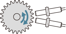 |
Conventional Products Two sensors are required to detect both forward and reverse rotation. |
 |
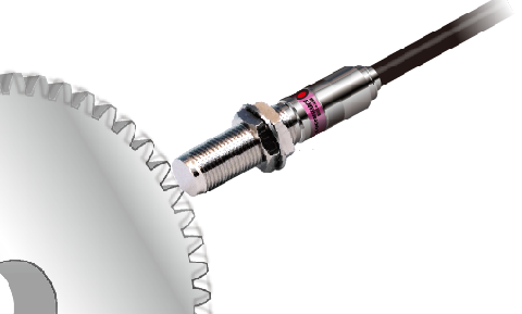
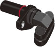
RFP16 Detects both forward and reverse rotation with a single sensor. |
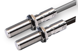
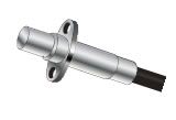
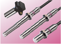
Metal case with integrated tip and body
Cable extraction technology Conical PressTM

Sensor Detection Surface / Conical PressTM
Verify the installation angle for each gear module with a single card
Align the card arrow with the forward rotation direction of the gear for verification.
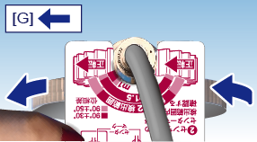
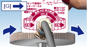
G: Forward rotation direction of the gear
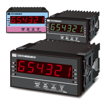
[RFP16A-85] A/B phase signal output
[RFP16D-85] Speed / direction detection signal output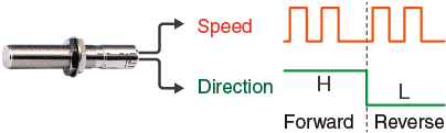
Offers high design flexibility and reduces management costs
Allows detailed monitoring of start and stop movements.
Output circuit uses a proprietary semi-open collector method, no pull-up required
| Name | Magnetic Gear Speed Sensor with Direction Detection | |
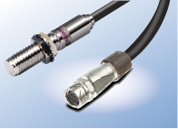
| Model | RFP16A-85 RFP16A-85-P4M [with connecter] |
RFP16D-85 RFP16D-85-P4M [with connecter] |
| Output Signal*1 | Phase A / Phase B Signal *2 | Speed / Direction Signal (Forward: H level, Reverse: L level) *2 |
| Output circuit | Semi-open collector (open collector + pull-up) |
|
| Pull-up Resistor | Phase A: 3.3kΩ / Phase B: 3.3kΩ | Speed Signal: 3.3kΩ / Direction Signal: 10kΩ |
| Detectable Object | Magnetic Material (S45C Carbon Steel for Mechanical Structures, JIS G 4051, etc.), Standard Involute Gear | |
| Detection Distance *3 | m1:0.1 - 1.0mm*3 / m1.5:0.1 - 2.0mm*3 / m2:0.1 - 2.7mm*3 | |
| Detectine Frequency *3 | 0 - 15kHz*3 | |
| Output Voltage | Output voltage approximately 0.5V lower than supply voltage | |
| Output Current | ≦ 30 mA (sink current) |
|
| Supply Voltag | DC7 - 25V | |
| Current Consumption | ≦ 40 mA | |
| Operating Temperature *4 | -40℃ - +140℃(for supply voltage <15V) / -40℃ - +126℃(for supply voltage ≧15V) |
-20℃ - +80℃ |
| Magnet Polarity at Tip | South pole | |
| Operation-check LED | Orange LED: Phase A / Green LED: Phase B | Orange LED: Speed Signal |
| Insulation Resistance | ≧ 50 MΩ (between cable bundle and case at DC 500 V Megger) | |
| Withstand Voltage | AC 500 V, 50/60 Hz, 1 min between cable bundle and case | |
| Vibration / Shock Resistance | JIS E 4031:2013 (Railway vehicle products - vibration and shock test methods): Functional vibration test: X, Y, Z: 5.4 m/s2 rms, both directions per axis, 10 min each / Endurance vibration test: X, Y, Z: 30.6 m/s2 rms, 5 h per axis / Shock test: 300 m/s2, total 18 times (3 positive and 3 negative shocks per orthogonal axis) |
|
| Temperature Test | JIS C 60068-2-14:2011 | |
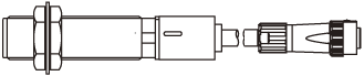
| Dimensions | M16(P=1 thread) x L84 | |
| Mass*5 | RFP16A-85:Approx. 230g / RFP16A-85-P4M:Approx. 250g (including cable approx. 65g/m)) |
RFP16D-85:Approx. 230g / RFP16D-85-P4M:Approx. 250g (including cable approx. 65g/m) |
| Case Material | Brass (nickel-plated) | |
| Cable(PVC) | 2 m 4-core shielded cable conductor 0.3 sq |
|
| Accessories | 2 nuts, 1 serrated washer, 1 setting card | |
| Protection Rating | IP67 | |
| RoHS | RoHS Compliance | |
| Price (Excl. Tax) *As of February 2024 |
RFP16A-85: 41,800yen RFP16D-85: 41,800yen |
RFP16A-85-P4M: 44,000yen RFP16D-85-P4M: 44,000yen |
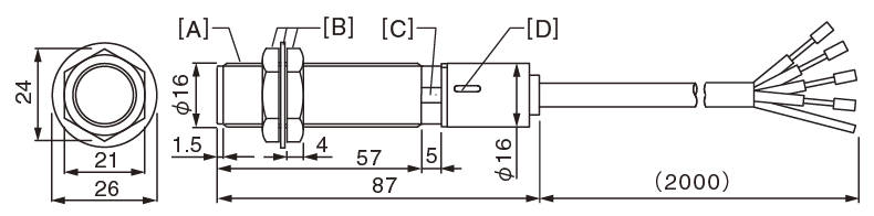
Brown: +V
Blue: 0V
White: Phase A SIG
Black: Phase B SIG
Shield: Insulated from main body
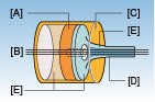
[A] M16 P=1 Thread
[B] Included Nut & Serrated Washer
[C] Surface for
14mm wrench
[D] Operation LED: Phase A / Back Side Phase B
Brown: +V
Blue: 0V
White: Speed SIG
Green: Direction SIG
Shield: Insulated from main body
[A] M16 P=1 Thread
[B] Included Nut & Serrated Washer
[C] Surface for
14mm wrench
[D] Operation LED: Speed SIG
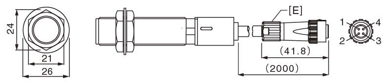
1 +V
2 0V
3 Phase A SIG
4 Phase B SIG
Shield connected via connector shell
[E] LF10WBPD-4P Connector Male*
*Hirose Electric Connector
1 +V
2 0V
3 Speed SIG
4 Direction SIG
Shield connected via connector shell
[E] LF10WBPD-4P Connector Male*
*Hirose Electric Connector
|
| Extension Cable Model | |||
| Cable Length 5m | Cable Length 10m | Cable Length 20m | |
| CY-RA-005 | CY-RA-010 | CY-RA-020 | For RFP16A-85-P4M |
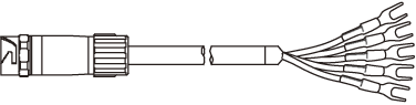 |
Brown: +V Blue: 0V White: Phase A SIG Black: Phase B SIG Shield: Insulated from main body |
||
| LF10WBJ-4S* 4-pin Female | Y-type crimp terminal 1.25Y-3 | ||
| CY-RD-005 | CY-RD-010 | CY-RD-020 | For RFP16D-85-P4M |
|
Brown: +V Blue: 0V White: Speed SIG Green: Direction SIG Shield: Insulated from main body |
||
| LF10WBJ-4S* 4-pin Female | Y-type crimp terminal 1.25Y-3 | ||
| CC-RP-005 | CC-RP-010 | CC-RP-020 | Common for RFP16A/D-85-P4M |
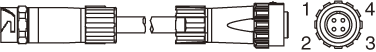 |
1: +V 2: 0V 3: Phase A / Speed SIG 4: Phase B / Direction SIG Shield connected via connector shell |
||
| LF10WBJ-4S* 4-pin Female | LF10WBPD-4P* 4-pin Male | ||
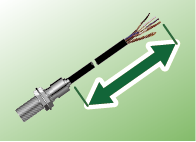
Extending the sensor cable increases susceptibility to external noise.
The impact depends on conditions, so it is recommended to verify performance in the user's environment.