・Specify calculation formulas (addition, subtraction, averaging, etc.) (Please inquire)
・Input/output values can be scaled arbitrarily
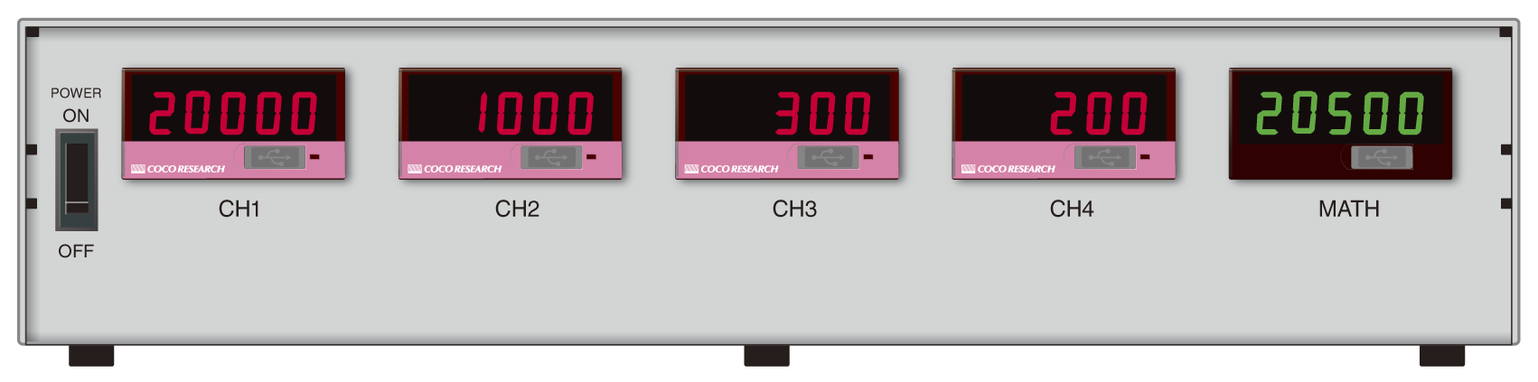
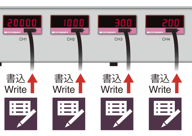
・Simultaneous display of each channel's input value and calculated value
・Printed content (e.g., CH1-4 or MATH notation) can also be specified
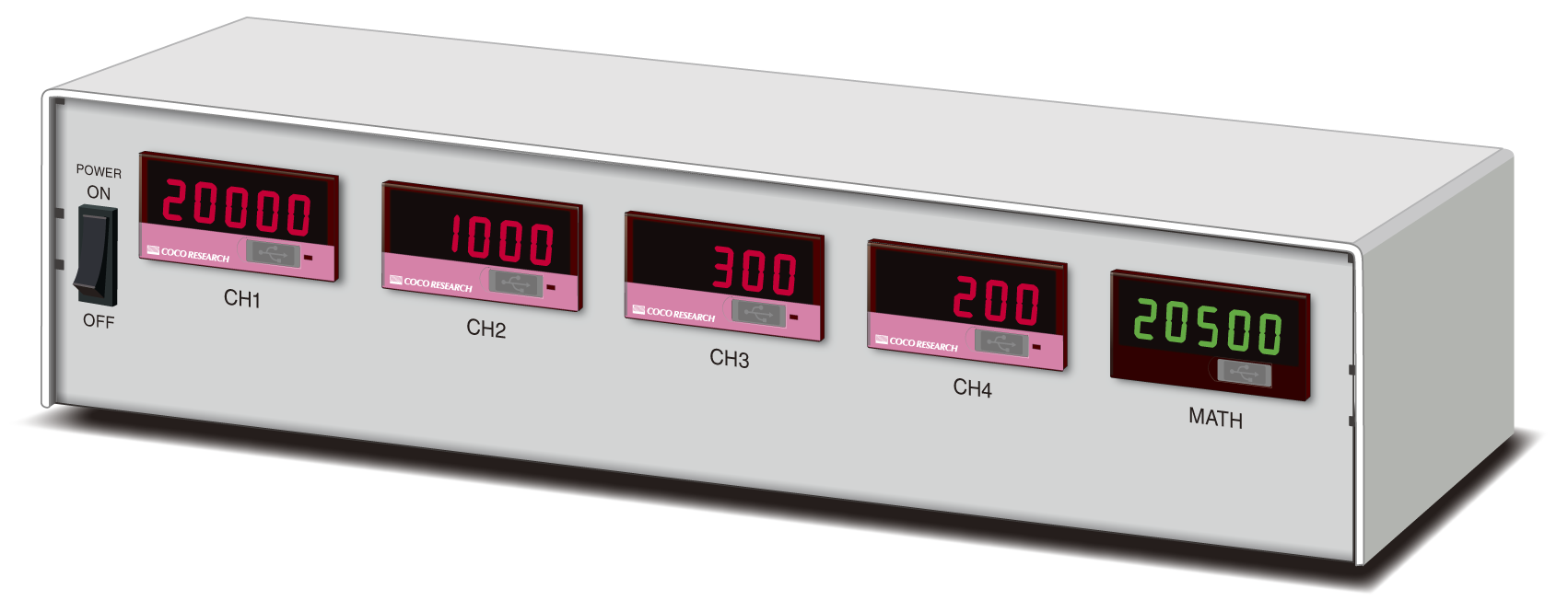
| CH1-4 | Input value CH1-4 | Flow Rate 1-4 |
| MATH | Output value after calculation | Net Flow Rate |
| Calculation | (CH1xCH2) - (CH3xCH4)= MATH | |
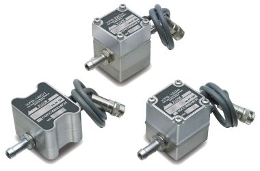
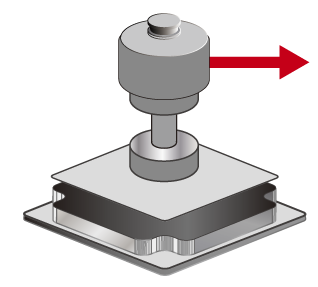
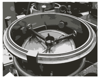
Flow Sensor 1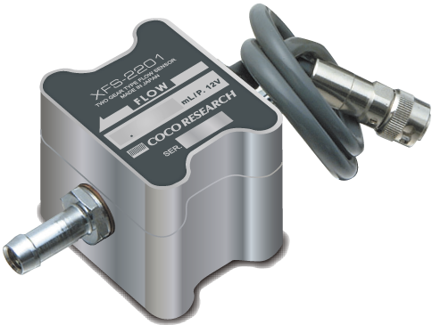 |
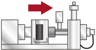
Flow Sensor 2 |
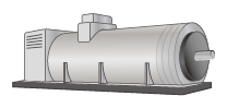
Flow Sensor 3 |
Flow Sensor 4 |
|||||
|
|
|
|
|||||
 |
|
|
|
 |
 Display/Analog Output
|


| Please inquire |
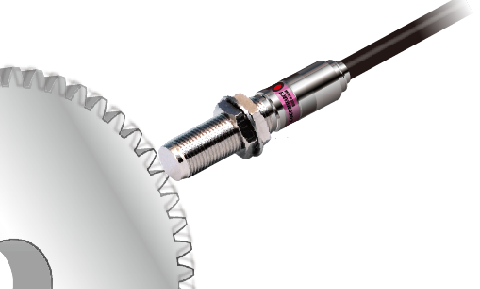
| Speed [Frequency pulse] |
| Torque [Frequency pulse] |
| Flow rate/Flow velocity |
| Angle/Position/Displacement/Integration |
| Current |
| Voltage |
| Temperature |
| Resistance |
0-10V / 0-5V / ±10V / ±5V / 4-20mA *Specify at time of order
Output Update: Configurable from 40ms to 9999ms
Full-scale, zero-scale, and offset settings available; zero adjustment possible
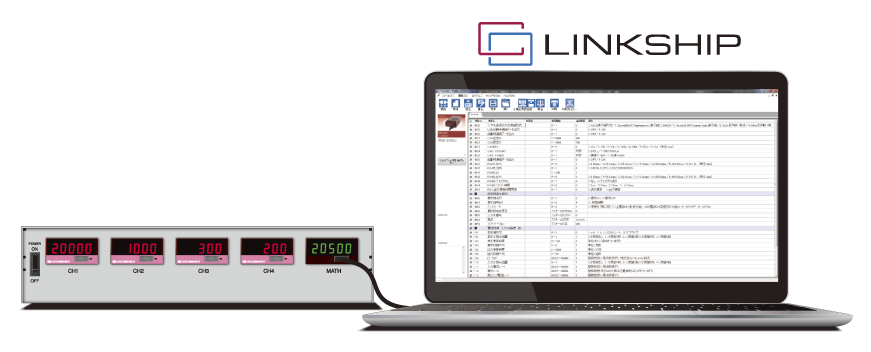
| > To the LINKSHIP page |
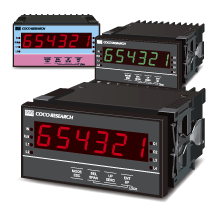
| Name | 4ch digital indicator | ||
| Input Section | |||
| Model | SPDL-2401 | ||
| Measurement Method | PeriomaticTMB (Periodic Calculation Method) | ||
| Number of Input Points | 1 point x 4 units(CH1 - 4) | ||
| Input Frequency | 0.0006Hz - 1.0MHz | ||
| Input Resolution | Approx. 10.4ns (96MHz) | ||
| Input Signal | |||
| General-purpose Input (Single-phase) | |||
| Level, Sensitivity | Trigger Level | Hysteresis | |
| 5V Logic | 2.5V | ±0.4V | |
| Zero-cross | 0V | ±0.03V | |
| NPN Open Collector | 2.5V | ±0.4V | |
| 12V Logic | 6V | ±0.4V | |
| Input Customization Signal | 0-9.0V Set in 10mV increments |
Small ±0.03V Medium ±0.4V Large(trigger level 4.7V or lower) ±1.3V (Trigger level 4.7V or higher) ±2.6V |
|
| Input Pulse | Hysteresis Small, Medium: 0.2μs or more; Large: 0.3μs or more (both H and L levels) | ||
| Input Resistance | 5V logic, zero-crossing, NPN open collector, input custom signal (trigger level 4.7V or less) :10kΩ 12V logic, input customization signal (trigger level 4.71V or higher) :5kΩ |
||
| Input Withstand Voltage | ±30V | ||
| Input Low-Pass Filter | OFF/500/5k/120k/800kHz selectable | ||
| Trigger Edge | Falling edge | ||
| Connector | Spring-lock plug connector [Option] M2 screw-type plug connector Fixed connector available *Please inquire |
||
| Sensor power output | DC+12V±5% 120mA max (Input power pass-through method) |
||
| Processing Unit | |||
| Measurement Mode | Speedometer / Frequency Meter / Period Meter (seconds only) / Totalizer [Switchable] | ||
| Processing Rate | Set reference pulse count, reference change amount, and speed unit time relative to input frequency | ||
| Division Ratio | 1 - 60000 (Effective for single-phase signals) | ||
| Moving Average | 1 - 99(Output moving average) | ||
| Dynamic PredictionTM | 8 levels (Includes continuous prediction and stop prediction) | ||
| Low Cut | Stop determination at speeds below the set value | ||
| Display Section | |||
| Display: Numeric | 7-segment 5-digit, 9mm character height, red, can be turned off / Option: green | ||
| Display Range | -19999 ~ 99999 Overrange Display: OL Zero Display: Leading zero suppression |
||
| Indicator | 1 point(selectable from Power/Trigger/Comparator Output) | ||
| Decimal Point Position | Set in Program Mode 0:□□□□□(No Decimal Point) 1:□□□□.□ ~ 4:□.□□□□ |
||
| Display Update | 0.3 seconds (Adjustable from 0.1 to 9.9 seconds) | ||
| Display Accuracy | 20ppm±1digit | ||
| USB Communication Section | |||
| Communication Specification | USB2.0 (Serial port communication via USB virtual COM at 230.4 kbps) | ||
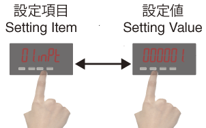
| Communication Functions | Setting value write/read / Continuous measurement value output | ||
| Output Update | 40ms - 9999.9ms Adjustable in 0.1 ms increments | ||
| General Specifications | |||
| Power Supply Voltage | +9V to +30VDC | ||
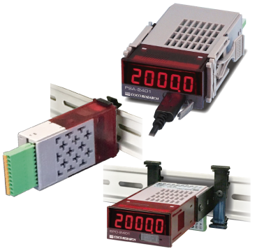
| Unit Dimensions | W323 H70 D88 *Excluding feet and protrusions Please inquire about other enclosures |
||
| Analog Options | |||
| Output Signal | 0-10V / 0-5V / ±10V / ±5V / 4-20mA 【Select at Order】 |
||
| D/A Conversion | DAC conversion method | ||
| Output Resolution | 16-bit (over 50,000 counts per range) | ||
| Output Scaling | Full-scale or zero-scale setting allows arbitrary scaling | ||
| Load Resistance | Voltage Output: 4.7kΩ or higher / Current Output: 300Ω or lower | ||
| Output Accuracy | Voltage Output: ±0.1% of FS@23℃ / Current Output: ±0.3% of FS@23℃ | ||
| Temperature Drift | ±200ppm/℃ or less | ||
| Output Update | 40ms - 9999.9ms adjustable in 0.1ms increments | ||
| Input/Output Delay Time | Output update time + analog rise time ≤ 150μs | ||
| Comparator Output Options | |||
| Setting Method | Set in Program Mode | ||
| Number of Outputs | 2-4 points (depending on model) | ||
| Output Type | Isolated contactless output (photomos relay) Non-polarized When comparator operating condition is ON, resistance between COMP and COM must be 50Ω or less |
||
| Output Load Voltage | Peak AC/DC 280V 100mA (resistive load) ON Resistance: 50Ω or less maximum | ||
| Output Logic | Polarity comparison (0 is greater than negative) Above: ON when above set value Below: ON when below set value Within Range: ON within set range, OFF outside range Outside Range: ON outside set range, OFF within range |
||
| Update Time | Depends on analog output update time setting; Response (max) | ||
| View more > |
| Load cell/Pressure/Strain | CAN to analog |
| DC current | DC voltage |
| Thermocouple meter | Thermistor meter |
| RTD meter | Resistance Meter |
| Speed/Count, Pulse Freq. | Torque/Freq.deviation |
Various Outputs
Software LINKSHIP
For data logging, setting
Customization
EX48
EX(L)24