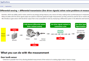
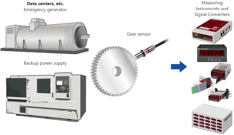
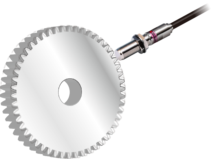
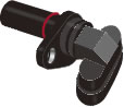
Composed of Hall elements, a magnet, and signal processing circuitry, it converts magnetic variations caused by rotation of a ferromagnetic detection gear into electrical signals for logic output.
Capable of detection from 0 Hz, with jitter suppression technology enabling precise rotation measurement.
A line driver output type is available for stable operation even with long wiring distances.
Equipped with a reverse-connection protection circuit to prevent failures caused by wiring mistakes.
Accurate detection from start to stop of movement.
Stable detection even in high-temperature environments.
Contact us for models with extended temperature ranges.
 ﹛
﹛
- Line driver output
- Semi-open collector output
(open collector + pull-up﹌
- Differential (balanced) CMOS logic output
Can detect ferromagnetic gears of module m0.5 or larger, and ferromagnetic objects with uneven surfaces (1-2 teeth, holes, etc.).
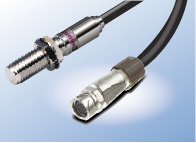
| Models | IMG12-50S IMG16-50S IMG12-50S-J6M IMG16-50S-J6M [J6M: with connector]  |
IMG12-50LD IMG16-50LD IMG12-50LD-J6M IMG16-50LD-J6M [J6M: with connector]  |
IMG12-50D IMG16-50D IMG12-50D-J6M IMG16-50D-J6M [J6M: with connector]  |
| Output circuits | Semi-open collector (open collector + pull-up) |
Line driver (equivalent to AM26LS31) |
Differential (balanced) CMOS logic output (can be used as unbalanced signal) ←1 |
| Pull-up Resistor | 800Ω | - | - |
| Detectable Object | Material: Ferromagnetic material such as S45C structural carbon steel (JIS G 4051) Standard gears and objects with steps of 3 mm or more |
||
| Detection Distance ←2 | [m0.5] 0.1-0.3mm / [m1] 0.1-1.3mm / [m2] 0.1-2.7mm / [m2.5] 0.1-3.0mm [m means module] | ||
| Allowable Mounting Angle Tolerance | ±20° | ||
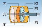
| Detection Element | 2-Hall-element differential method | ||
| Response Frequency | 0 - 20kHz | ||
| Output Voltage | Approximately 0.5 V lower than supply | H ⊥ 2 V / L ∪ 0.8 V (no load) | Output at supply voltage |
| Output Current | ∪﹛60 mA (sink current) |
Approx. 10 mA (with 100 次 load) |
Supply 5 V: 0.72 mA Supply 15 V: 4.8 mA |
| Supply Voltage | 4.5 - 25VDC | 4.5 - 25VDC | 4.5 - 17VDC |
| Current Consumption | ∪ 0 mA ﹋LED ON﹌ |
∪ 20 mA (with 100 次 load, LED ON) |
∪ 20 mA (LED ON) |
| Operating Temperature | -20 - +105∵ ←3 | ||
| Magnet Polarity at Tip | South pole | ||
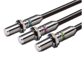
| Operation-check LED | Red LED | ||
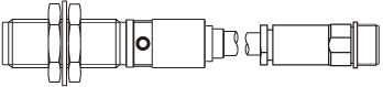
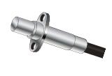
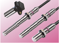
| Dimensions | [IMG12] M12(P=1thread)x L58 [IMG16] M16(P=1thread)x L58 |
||
| Case Material | Brass (nickel-plated) | ||
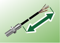
| Cable(PVC) | 2 m 3-core shielded cable conductor 0.2 sq |
2 m 2-pair (4-core) shielded cable conductor 0.2 sq |
|
| Insulation Resistance | ⊥ 50 M次 (between cable bundle and case at DC 500 V Megger) | ||
| Withstand Voltage | AC 500 V, 50/60 Hz, 1 min between cable bundle and case | ||
| Vibration / Shock Resistance | JIS E 4031:2013 ﹋Railway vehicle products - vibration and shock test methods﹌“ Functional vibration test: X, Y, Z: 5.4 m/s2 rms, both directions per axis, 10 min each / Endurance vibration test: X, Y, Z: 30.6 m/s2 rms, 5 h per axis / Shock test: 300 m/s2, total 18 times (3 positive and 3 negative shocks per orthogonal axis) |
||
| Temperature Test | JIS C 60068-2-14:2011 | ||
| Mass ←4 | [IMG12] Approx. 130 g﹛[IMG12-***-J6M] Approx.150 g (cable: 50 g/m) [IMG16] Approx.160 g﹛[IMG16-***-J6M] Approx. 180 g (cable: 65 g/m) |
||
| Accessories | 2 nuts, 1 serrated washer | ||
| Protection Rating | IP67 | ||
| RoHS | RoHS Compliance | ||
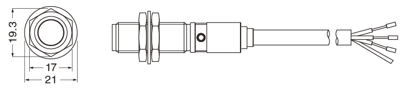
Brown: +V
White: SIG OUT 1
Black: SIG OUT 2
Blue: 0V
Shield: Insulated from main body
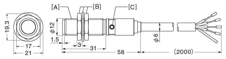
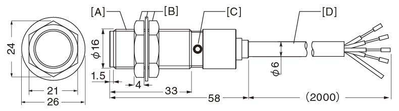
[A] M12 P=1 Thread
[B] Included Nut & Serrated Washer
[C] Operation-check LED / Alignment Mark
Brown: +V
Black: SIG OUT
Blue: 0V
Shield: Insulated from main body
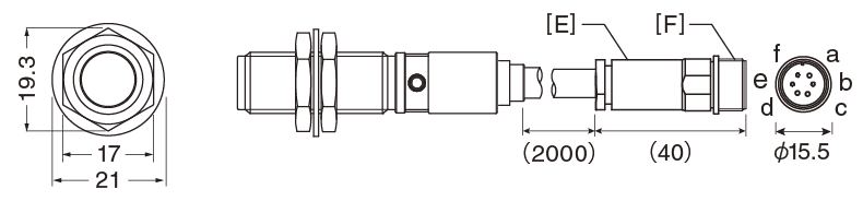
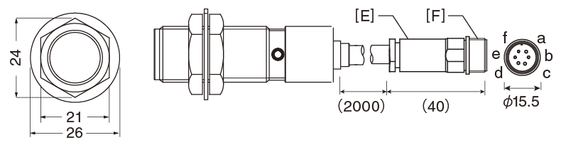
a: SIG OUT 1
b: SIG OUT 2**
c: +V
d: Shield
e: 0V
f: Empty (cannot be connected)
[E] R04-J6M Connector Round 6P (Male)*
[F] M14 P=1 Thread
*Connector by Tajimi Musen Denki Co., Ltd.
**IMG12-50S-J6M: empty>
Brown: +V
White: SIG OUT 1
Black: SIG OUT 2
Blue: 0V
Shield: Insulated from main body
[A] M12 P=1 Thread
[B] Included Nut & Serrated Washer
[C] Operation-check LED / Alignment Mark
[D] Shielded Cable
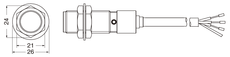
Brown: +V
Black: SIG OUT
Blue: 0V
Shield: Insulated from main body
a: SIG OUT 1
b: SIG OUT 2**
c: +V
d: Shield
e: 0V
f: Empty (cannot be connected)
[E] R04-J6M Connector Round 6P (Male)*
[F] M14 P=1 Thread
*Connector by Tajimi Musen Denki Co., Ltd.
**IMG16-50S-J6M: empty
|
| Extension Cable Model | Cable End | ||
| Cable Length 5m | Cable Length 10m | Cable Length 20m | |
| DK-005 | DK-010 | DK-020 | Y-type Crimp Terminal |
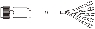 |
White: SIG OUT 1 Black: SIG OUT 2** Brown: +V Blue: 0V Shield |
||
| R04-P6F* 6-Pin Female | Y-type Crimp Terminal 1.25Y-3 | ||
| DK-005T | DK-010T | DK-020T | Plug Connector |
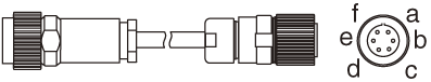 |
a: SIG OUT 1 b: SIG OUT 2** c: +V d: Shield e: 0V f: Empty |
||
| R04-P6F* 6-Pin Female | R03-P6M* 6-Pin Male | ||