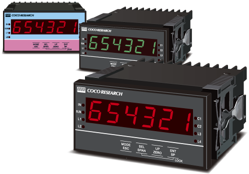
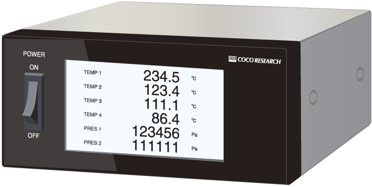
An ideal voltmeter for evaluation, testing, and control processes that demand high-precision DC voltage measurement.
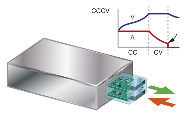
It is perfectly suited for charge/discharge evaluation of rechargeable batteries and various testing applications requiring continuous voltage monitoring.
- Measures the average voltage per output update time using a Delta-Sigma A/D converter with approx. 250kHz oversampling.
- Rate settings can be configured arbitrarily.
- Functions as a scaling meter with a variety of input ranges, hold, and control capabilities.
Want to check if this product fits your application? 24x48 Size Selection Guide 48x96 Size Selection Guide Model Selection for This Unit |
| INPUT Voltage Signals |
|
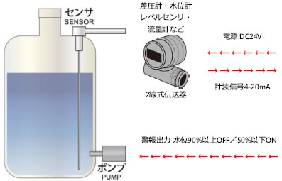
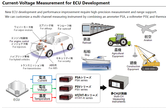
Pressure sensors, Displacement sensors, ECUs, Level sensors, etc.     |
 |
| Sensor Power Supply ・12V / 5V / Others |
 |
| PROCESSING ・250kHz Oversampling ・Moving Average: Max 99 ... Low-Cut ・HOLD [Current / Max / Min / Max Peak-to-Peak] ・Zero/Span Shift, Zero/Span Set |
||
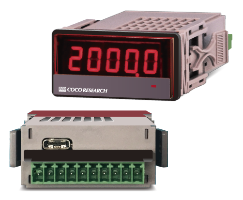
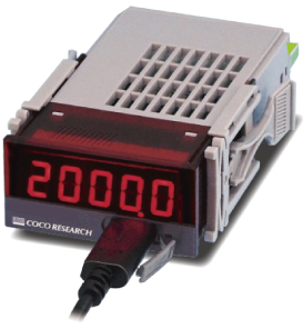
PSV-24 Series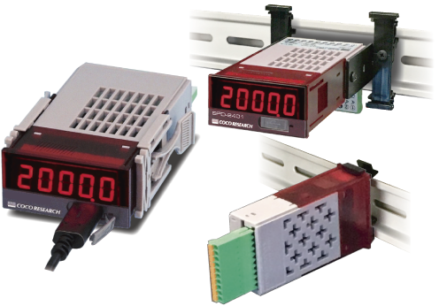 |
|
|
| Power ・7–60V DC ・5V USB Bus Power |
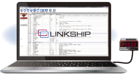
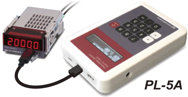
Configuration ・LINKSHIP Software ・PL-5A Handy Configurator |
|
| OUTPUT | |||||||
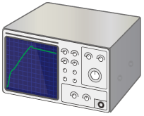
PCs, PLCs, Loggers, Oscilloscopes, Indicators, etc.  
   |
|||||||
| ±70V |
| ±30V |
| ±20V |
| ±10V |
| ±5V |
| ±2V |
| ±1V |
| ±200mV |
| ±100mV |
| ±20mV |
| ±10mV |
| 1(0)-5V* |
| 0-10V* |
| *Process signal compatible |
| DC Voltage Measurement |
| Pressure Measurement |
| Displacement Measurement |
| Voltage-to-CAN Conversion |
| Flow Measurement |
| View Details > |
| Voltage → CAN |
| Pressure / Displacement / Level sensors, various voltage-output sensors, and process signals (e.g., 1-5V) |
|
| View Details > |
| View Details > |
| View Model Selection Table > |
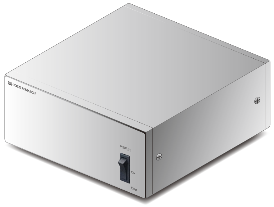
| PSV-2401 Display Only |
| From 32,500 JPY (excl. tax) |
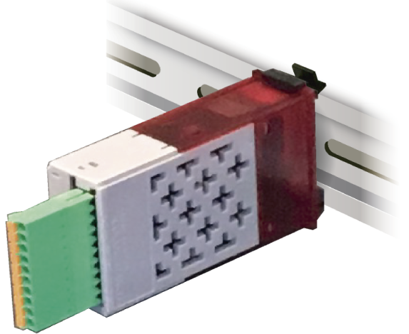
| PSV-2451 DIN Rail Mount, No Display |
| From 28,100 JPY (excl. tax) |
| Options & Prices |
| Low-Cost Version Page |
| Voltage Measurement List |
| View Case Studies > |
| View 40ms Type > |
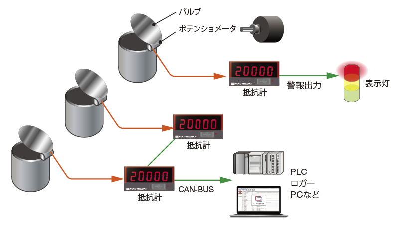
3-wire wiring significantly reduces cables compared to BCD.
Powerful error detection system ensures high noise immunity and improved safety.
| SAE J1939 (DLC 8 bytes or less) Customization Examples Available Please contact us for other types of customization. |
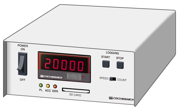
RS-485 [Option]
USB Type-C [Standard] Data Logging & Configuration
Resolution: 50,000 or higher, Full/Zero scale configuration, Analog output zero adjustment
Dual Analog Outputs Available [NEW] [Option]Dual analog output option is now available. Example: Simultaneous 0-10V and 4-20mA outputs.
Alarm Output [Option] 1 to 4 points
| Go to LINKSHIP Page > |
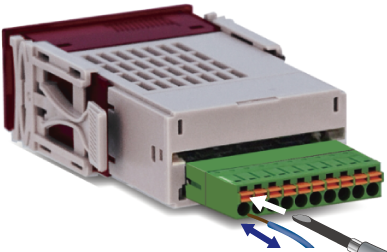
[Detachable Plug Connectors]
Just wire the connector and plug it in
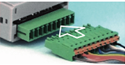
Detachable Plug Connector
Spring-lock type [Standard]
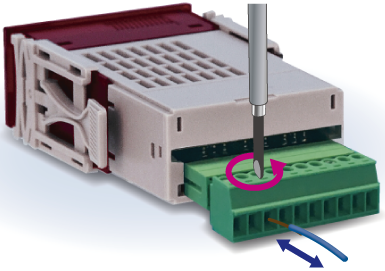
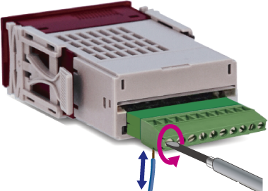
Detachable Plug Connector
M2 screw type [Option]
Fixed Connector also available
[Custom Support]
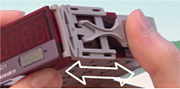
Easy attachment/detachment
Mounting Hooks (Left & Right)
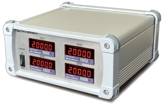
Carry your PC/tablet, this device, and cables to measure anywhere via USB bus power. Optional carrying case BXS-1 is also available.
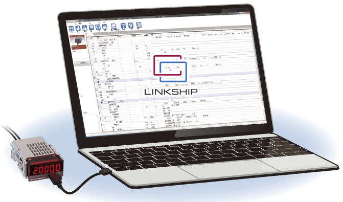 |
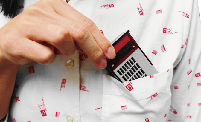  > View BXS-1 Overview |
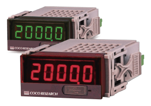
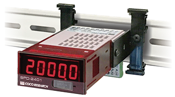
Ultra-compact 24x48 size contributes to space-saving equipment design.
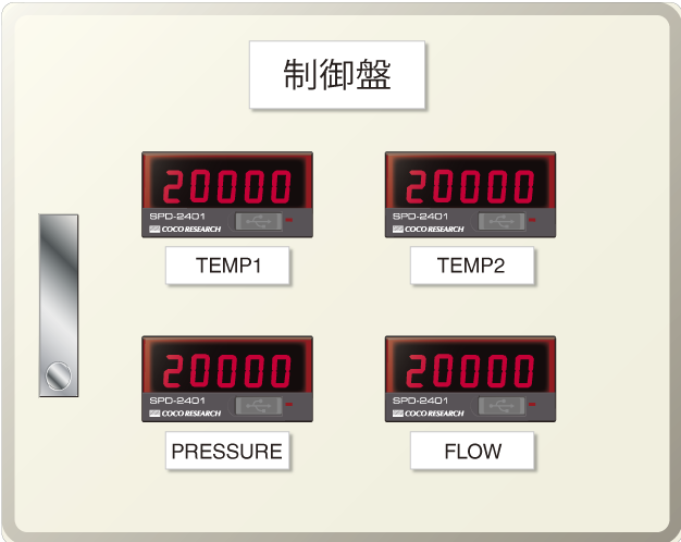
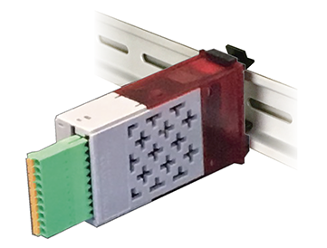
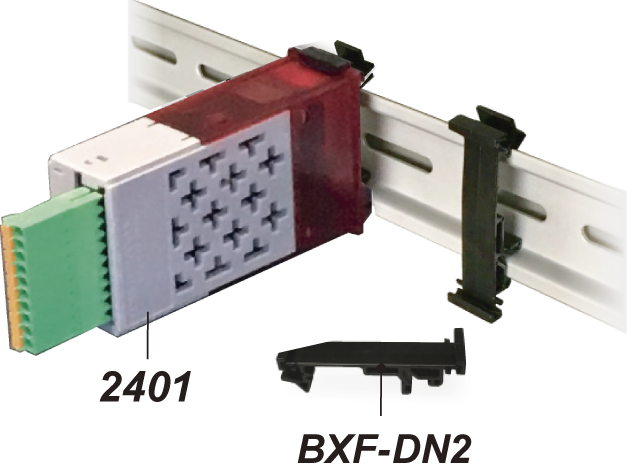
One-touch mounting fixtures and models without display are available.
 |
 |
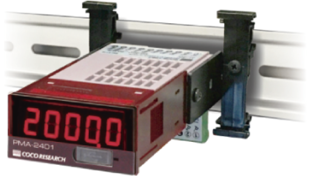 |
| BXF-DN2 DIN Rail Mounting Fixture (Sold separately) |
PSV-2451 Without Display |
PSV-2431 With Display |
| > Go to BXF-DN2 Page | > View details for 2451 and 2431 | |
| View Specs > | Model / Options > |
| Model | PSV-2401 / PSV-2411 / PSV-2431 / PSV-2451 | ||||||||||||||||||||||||||||
| Input Signal | DC Voltage Signal | ||||||||||||||||||||||||||||
| Operation Method | ΔΣ (Delta-Sigma) Integration Method | ||||||||||||||||||||||||||||
| Input Section | |||||||||||||||||||||||||||||
| Number of Inputs | 1 point | ||||||||||||||||||||||||||||
| Measurement Range |
|
||||||||||||||||||||||||||||
| Accuracy | ±0.1% FS + 1 digit | ||||||||||||||||||||||||||||
| Oversampling | Fixed at 250kHz | ||||||||||||||||||||||||||||
| Input Low-Pass Filter | Cut-off frequency: 1kHz | ||||||||||||||||||||||||||||
| Sensor Power Output | Option: [H] 12V DC ±5%, 60mA max / [L] 5V DC ±5%, 150mA max (Sensor power is not output during USB power supply) |
||||||||||||||||||||||||||||
| Arithmetic / Processing Section | |||||||||||||||||||||||||||||
| Moving Average Count | 1 - 99 | ||||||||||||||||||||||||||||
| Low-Cut | Evaluated as 0 for voltage values below the set threshold | ||||||||||||||||||||||||||||
| Control Input | None or 1 point (depending on model) / 2 points added with [D2] option | ||||||||||||||||||||||||||||
| (Configuration) | Functions are configured for each control input (CTL) and controlled externally. [Functions] Hold (Current, Max, Min, Max Peak-to-Peak), Zero Shift, Span Shift, Zero Set, Span Set [ON Logic] Normally Open, Normally Closed |
||||||||||||||||||||||||||||
| (Operation Method) | The function is applied by short-circuiting (or opening) the control input (CTL*) terminal (ON logic) to GND. | ||||||||||||||||||||||||||||
| (Data Communication) | Command control is available via communication (USB, CAN, RS-485). *Commands set via communication cannot be canceled via terminal input. A hardware reset is required. | ||||||||||||||||||||||||||||
| Control Input Response | Configurable response time (1ms to 1999ms) | ||||||||||||||||||||||||||||
| Control Input Backup | Enable/disable backup for Shift and Set operations (retains values even when powered OFF) | ||||||||||||||||||||||||||||
| Memory Storage | Non-volatile memory (EEPROM) |
||||||||||||||||||||||||||||
| Display Section | |||||||||||||||||||||||||||||
| Display (Numeric) | 5-digit, 7-segment LED, character height 9mm | PSV-2401: Red LED / PSV-2401-G: Green LED (Option) Display Range: -19999 to 99999 | Polarity Display: "-" lights up during reverse rotation Over-range Display: OL | Zero Display: Leading zero suppression Display Update Time: 0.3 sec (configurable within 0.1 to 9.9 sec) | Display Accuracy: 20ppm ± 1 digit at 23℃ |
||||||||||||||||||||||||||||
| Decimal Point Position | Semi-fixed, configured in program mode. 0: □□□□□ | 1: □□□□.□ to 4: □.□□□□ | ||||||||||||||||||||||||||||
| Display (Indicator) | 1 LED, configured from Power / Control Input |
||||||||||||||||||||||||||||
| USB Communication Section | |||||||||||||||||||||||||||||
| USB Comm. Specs | USB 2.0 (Serial port communication via USB Virtual COM, 230.4kbps) | ||||||||||||||||||||||||||||
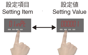
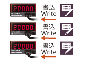
| USB Comm. Functions | Read/Write configuration values / Continuous measurement data output | ||||||||||||||||||||||||||||
| Output Update Time | 1ms - 9999ms (configurable in 1ms increments) |
||||||||||||||||||||||||||||
| General Specifications | |||||||||||||||||||||||||||||
| Operating Temp/Humidity | -10℃ to +50℃, 35 to 85% RH (Non-condensing) | ||||||||||||||||||||||||||||
| Power Supply Voltage | 7–60V DC, Reverse connection protection included / Power supply from USB host: 5V | ||||||||||||||||||||||||||||
| Power Consumption | 3W or less | ||||||||||||||||||||||||||||
| Isolation | Between Power supply / Voltage input / Other inputs & outputs | ||||||||||||||||||||||||||||
| Weight | Approx. 60g |
||||||||||||||||||||||||||||
| CAN Option | |||||||||||||||||||||||||||||
| Communication Specs | CAN2.0B 10k / 20k / 50k / 100k / 250k / 500k / 1M bps | Format (INTEL/MOTOROLA), Frame (11bit/29bit) | ||||||||||||||||||||||||||||
| Communication Functions | Read/Write configuration values / Continuous measurement data output | ||||||||||||||||||||||||||||
| Configurable Items | CAN Tx ID, CAN Rx ID | ||||||||||||||||||||||||||||
| Output Update Time | 1ms - 9999ms (configurable in 1ms increments) |
||||||||||||||||||||||||||||
| RS-485 Option Please contact us for Modbus RTU compatibility. | |||||||||||||||||||||||||||||
| Max. Connections | 32 units (max) | ||||||||||||||||||||||||||||
| Communication Type | 2-wire multi-drop serial communication | ||||||||||||||||||||||||||||
| Synchronization Method | Asynchronous | ||||||||||||||||||||||||||||
| Communication Standard | RS-485 | ||||||||||||||||||||||||||||
| Baud Rate | 9600bps / 19200bps / 38400bps (configured in program mode) | ||||||||||||||||||||||||||||
| Data Format | Start bit: 1-bit / Stop bit: 1-bit / Data length: 8-bit / Parity bit: None | ||||||||||||||||||||||||||||
| Communication Code | ASCII | ||||||||||||||||||||||||||||
| Communication Functions | Read/Write configuration values / Measurement data output (responds to request commands) |
||||||||||||||||||||||||||||
| Analog Output Option | |||||||||||||||||||||||||||||
| Output Signal | [E1] 0 - 10V [E5] 0 - 5V [R1] ±10V [R5] ±5V [I1] 4 - 20mA 【Select Model】 | ||||||||||||||||||||||||||||
| D/A Conversion Method | DAC Method | ||||||||||||||||||||||||||||
| Output Resolution | 16-bit (50,000 or higher) | ||||||||||||||||||||||||||||
| Load Resistance | Voltage Output: 4.7kΩ or higher | Current Output: 300Ω or less | ||||||||||||||||||||||||||||
| Output Accuracy | Voltage Output: ±0.1% of FS at 23℃ | Current Output: ±0.1% of FS at 23℃ | ||||||||||||||||||||||||||||
| Temperature Drift | ±200ppm/℃ or less | ||||||||||||||||||||||||||||
| Output Scaling | Arbitrary scaling is possible via Full-scale and Zero-scale settings. | ||||||||||||||||||||||||||||
| Output Update Time | 1ms - 9999ms (configurable in 1ms increments) |
||||||||||||||||||||||||||||
| Comparator (Alarm) Output Option | |||||||||||||||||||||||||||||
| Configuration Method | Configured in program mode | ||||||||||||||||||||||||||||
| Number of Outputs | 2 points / 4 points (depending on model selection criteria) | ||||||||||||||||||||||||||||
| Output Type | Isolated solid-state output (PhotoMOS relay), non-polarized. Resistance between COMP-COM is 50Ω or less when comparator operation condition is ON. | ||||||||||||||||||||||||||||
| Output Load Voltage | Peak AC/DC 280V, 100mA (Resistive load) | Max ON resistance: 50Ω or less | ||||||||||||||||||||||||||||
| Output Logic | Comparison is performed with polarity (0 is greater than minus).
|
||||||||||||||||||||||||||||
| Update Time | Depends on the analog output update time settings. Response time: 1ms (max) | ||||||||||||||||||||||||||||
| Voltage Input List > | All Product List > |
- CAN Output
- 16-bit Analog (Voltage/Current) Output
- USB-C: Configuration & Data Logging
- Alarm Output / RS-485
- Configuration Management Software (Free): Report Printing & Data Logging
- Dual Analog Outputs [EX48]
- Ethernet (LAN) [EX48]