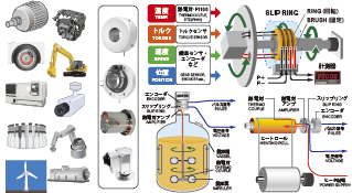
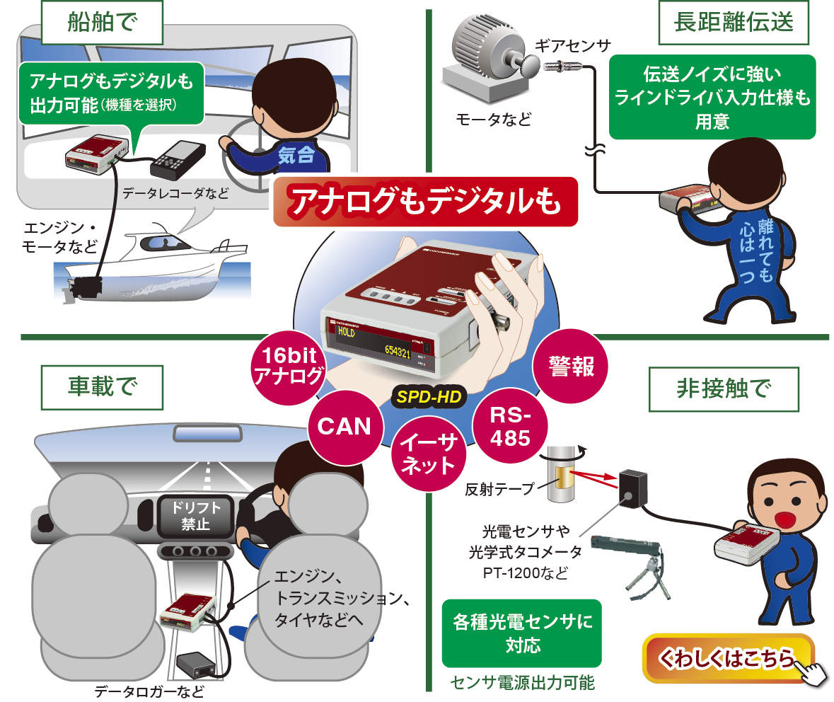
Measures the effects of wind on automobiles, motorcycles, and architectural/civil engineering structures within wind tunnel testing systems.
Simultaneously monitors wind speed along with rotational speed, temperature, current, voltage, resistance, and torque.
Utilizing scale models of architectural and civil engineering structures, it is also applicable for wind tunnel tests involving snow accumulation, fire smoke propagation, and thermal stratification.
 |
|
|||||||
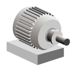
 Blower Fan |
 |
 Anemometer |
|
|||||
 |
||||||||
| Pulse Signal |  |
|
||||||
|
||||||||||||||||||||||
| High Precision & Rapid Response Powered by our unique Perio-MaticTM algorithm, delivering high precision from ultra-low to high speeds, and instantly tracking sudden variations in wind speed (Tachometer/Speedometer) 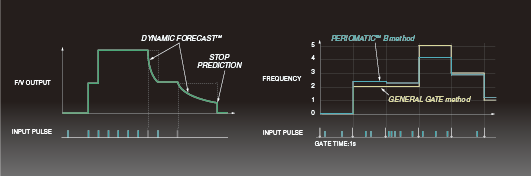 What is Perio-MaticTM? |
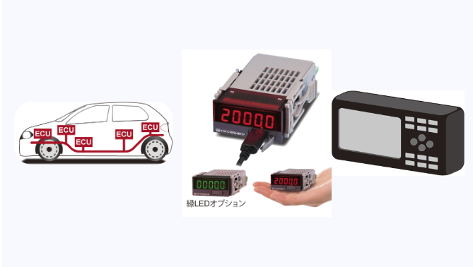
CAN Data Output (Option)
|
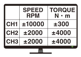
| Analog Output (Option) Output Update Rate: Fastest from 0.1 ms Output Signals (Specify at time of order)
Configurable Full-Scale Values |
| Warning / Alarm Output (Option) Triggers an output signal when the pre-configured rotation threshold is exceeded. |
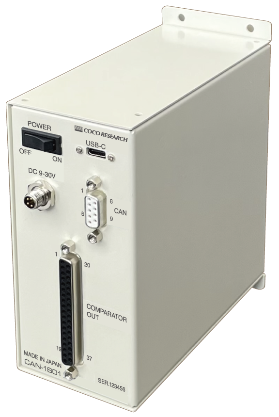
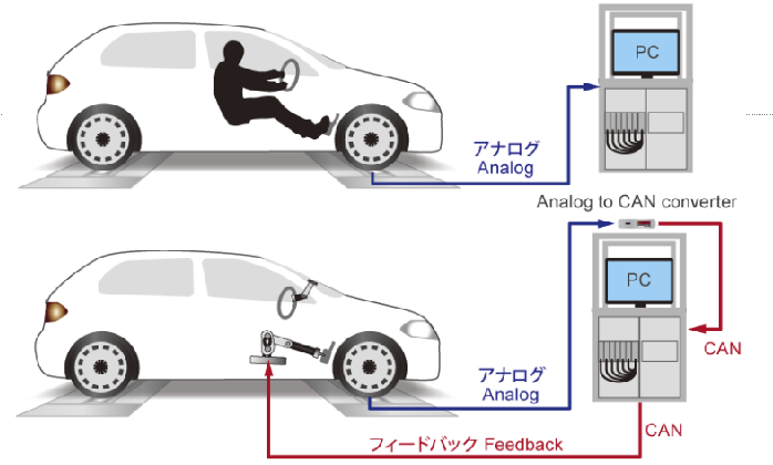
| CAN-to-Analog Conversion (CAN-Analog Converter) Converts vehicle CAN data directly into analog signals, eliminating the need for expensive CAN analyzers. |
| Consolidate 15-CH CAN Data into 1 CAN-ID (CAN Data Comparator/Output Unit) Performs comparative evaluation for each channel and provides contact outputs. |
| Proprietary Perio-Matic™ technology (Tachometers) |
| Extensive product line variations |
| High-speed update analog output |
| Ultra-fast 1 ms update CAN output |
| Effortless verification of specific CAN data (CAN-Analog Converter) |
| Full customization capability (multi-channel, dedicated enclosures, mixed sensor configurations, etc.) |
| Line driver input compatibility for noise immunity over long-distance transmissions (Tachometers / Torque Meters) |
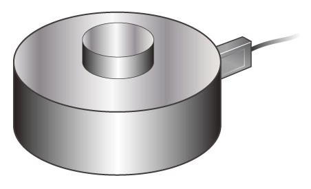
| Load Cell Input > | |||||||||
Excitation: 2.5V/5V/10V | Bridge: 120Ω/350Ω
|
| DC Current Input > | ||||||||
Supports ±100 μA to ±10 A
|
| DC Voltage Input > | ||||||||
Supports ±10 mV to ±70 V
|
| Resistance Input > | ||||
For displacement & resistance output sensors
|
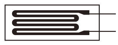
| Thermistor Input > |
High-precision conversion via proprietary math 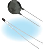 NTC Thermistor |
| Thermocouple Input > | |||
Supports Types K, J, R, E, T, B, N, S
|
| RTD Input > | ||
Supports Pt100 RTD Sensors
|
| Angle / Position / Displacement (Pulse Input) > | ||||||||
For length, angle, displacement, flow rate, etc.
|
| Speed (Frequency Pulse Input) > | ||||||||
High precision via Perio-MaticTM
|
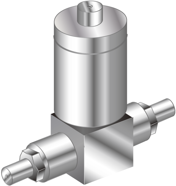
| Torque (Frequency Pulse Input) > | ||||
For torque & flex-fuel sensors
|
| CAN-to-Voltage Converters Available > | ||||||||
Converts CAN data into voltage signals or alarm signals
|
| Product List > |
| Series Lineup > |
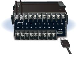
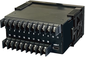
- CAN Output
- 16-bit Analog (Voltage/Current) Output
- USB-C: For Configuration & Data Logging
- Alarm Output / RS-485
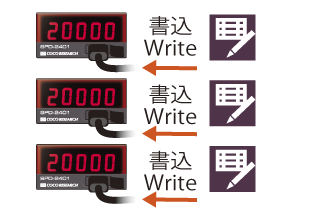
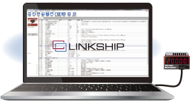
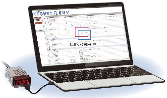
- Complimentary Setup Software: Report Printing & Data Logging
- Dual Analog Outputs [EX48]
- Ethernet (LAN) Connectivity [EX48]
| Load Cell/Pressure/Strain | CAN Conversion |
| DC Current | DC Voltage |
| Thermocouple (Temp) | Thermistor (Temp) |
| RTD (Temperature) | Resistance |
| Speed / Totalizer | Frequency Deviation/Torque |
 EX48: From 35,800 JPY |
 EX(L)24: From 15,100 JPY |
| > Go to LINKSHIP Page |
Front USB: Configuration, Logging, and Power Supply
Settings can also be configured via rear terminals*. Rear USB types are also available.*Configuration and logging via the rear terminal block require the CAN or RS-485 option.
*For Load Cell / Pressure Gauge ST(L), please supply power from the rear terminal block, not the USB connector.
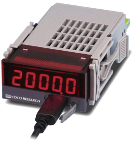
Rear USB: Configuration & Logging
Configuration is also possible via front buttons or rear terminal blocks.*Configuration and logging via the rear terminal block require the CAN or RS-485 option.
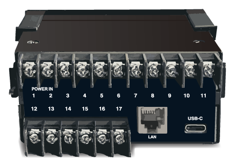 Ethernet (LAN) Option
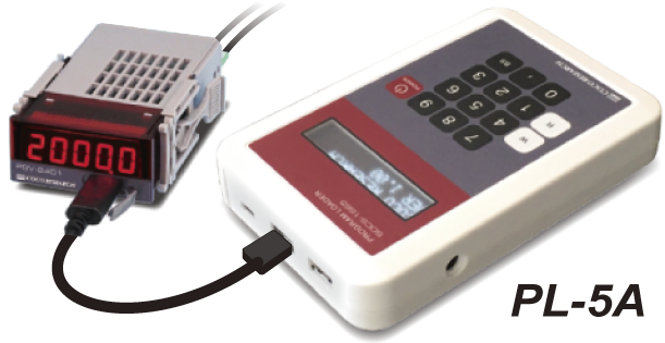
Standalone Setting Unit (No LINKSHIP or PC Required)
[Sold Separately]
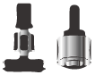
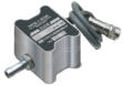
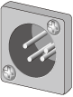
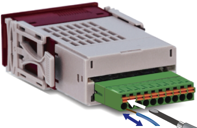
Detachable Plug Connector
Simply wire to the connector and plug it in
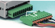
Detachable Plug Connector
Spring-lock Type [Standard]
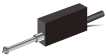
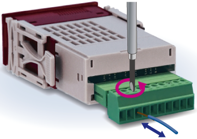
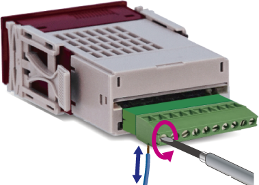
Detachable Plug Connector
M2 Screw Type [Option]
Fixed Connector
[Custom Support Available]
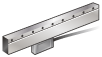
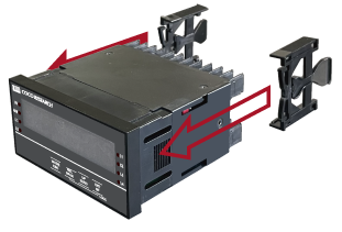
Mounting Hooks [Left/Right]
Easy unit attachment/detachment without tools

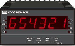
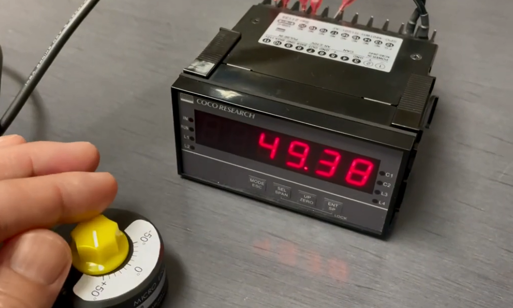
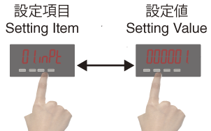
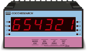
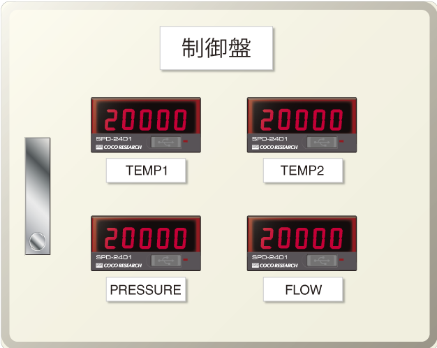
Front Panel Configuration & Measurement
Equipped with a key lock to prevent accidental operation
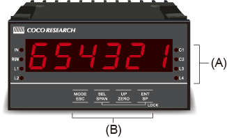
(A) Operation Indicator LED
(B) Front Sheet Buttons
[Program Mode]: MODE, Digit Selection, Value Configuration, ENTER
[Measurement Mode]: Span Shift, Zero Shift
Key Lock, etc.
 |
  > View BXS-1 Overview |
 |
 |
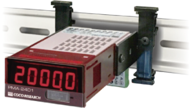 |
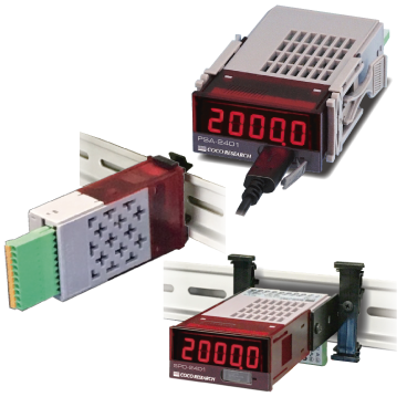
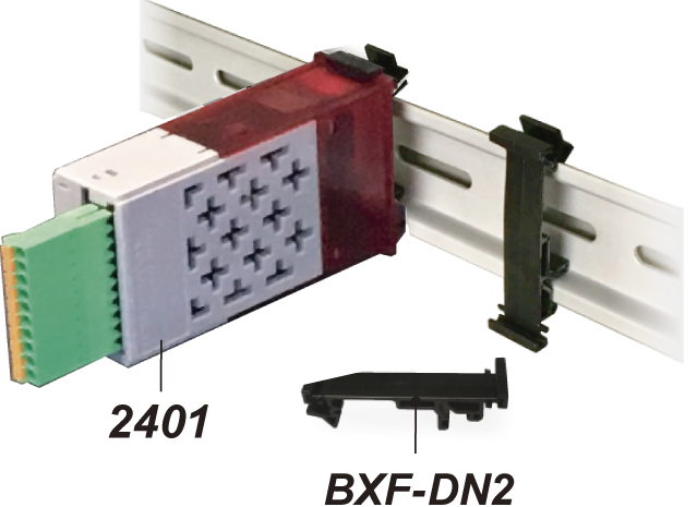
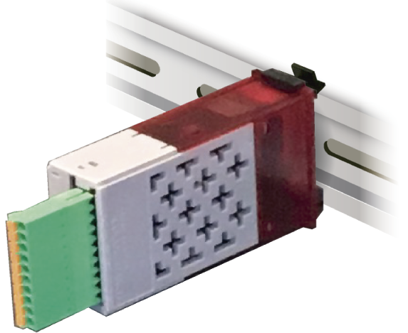
| BXF-DN2 DIN Rail Fixture (Sold Separately) |
2451 Type Without Display |
2431 Type With Display |
| > Go to BXF-DN2 Page | > See Descriptions for 2451 & 2431 | |
| > View Full List |
Enclosure Box Integration> Details 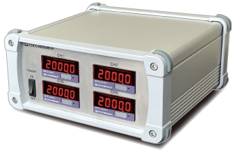 |
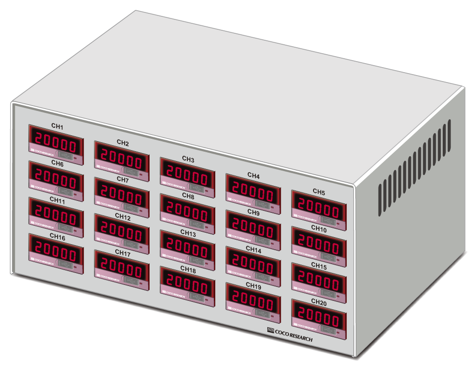
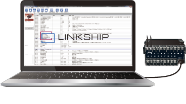
Multi-CH with Display> Details 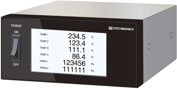 |
Multi-CH Radiation Thermometer (CAN Output)> Details 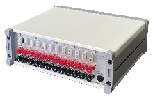 |
With SD Data Logger> Details 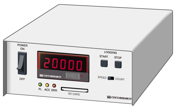 |
Rack Integration> Details 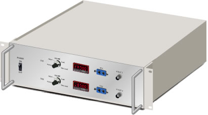 |
Handy Type> Details 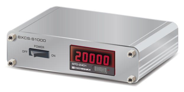 |
| Connectors | ||||||||||||||||||||||||||||||||
|
| Display | ||||||
|
| Power Supply | ||||
| ||||
| ||||
|
| View Application Examples List |