Applications
Transmission Testing
Rotation is detected from a gear sensor by mounting a gear on the shaft, etc., and the pulses are converted to analog signals.
Analog data is input to a logger, PC, oscilloscope, etc. for evaluation testing and development.。
Gear Sensor 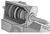 |
→ Pulse Signal |
 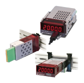 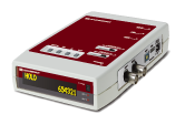 Measuring instrument |
→ Analog output Alarm output CAN RS-485 etc. |
 PC  Logger 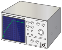 Oscilloscope etc. |
What we can do with measurement
- Rotation speed of each input and output can be measured.
- The unique Periomatic™ calculation method enables high speed response with high accuracy to startup from a standstill, ultra-low speed, high speed, and sudden speed changes (sudden acceleration, sudden stop).
- The FRM-3921 tachometer can also be used to measure the input/output ratio of the transmission.
- Independent rates can be set for the two input channels, allowing calculation of speed ratios even for gears with different numbers of teeth or sensors with different resolutions.
- With the PSA series DC ammeter, real-time measurement of PWM drive current of solenoid valves is also possible.
Gear tooth sensor
- The gear sensor is capable of detecting from 0Hz, allowing detailed measurement of motion at the start and at the stop of motion.
- The sensor uses a two Hall element differential method for the sensing section, so it is not affected by the surrounding magnetic field and can perform stable detection with reduced jitter.
- Line driver output option, which is less susceptible to transmission noise, is also available. (Gear sensor IMG series)
Selection Points
- Analog output update 0.1ms~(SPD), 0.5ms~(TDP), 1ms~(FRM)
- CAN, RS-485, RS-232C, Ethernet output also available
- Unique Periomatic™ calculation method: High-precision, high-speed response to start of motion from standstill, ultra-low speed, high-speed, and sudden speed change (sudden acceleration, sudden stop), etc.
- Optional line driver signal support: Highly resistant to transmission noise
- Gear sensor capable of sensing from low rotation speed (0 Hz)
| Products | Points | Overviews | |
|---|---|---|---|
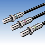 |
IMG Series Magnetic Gear Speed Sensor Product page |
Line driver output Semi-open collector output Differential (balanced) CMOS logic output Wide power supply range Conical press |
- Stable output by eliminating magnetic field noise and suppressing jitter in the detection section by using a two Hall element differential method.
|
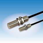 |
FDP Series Magnetic Gear Speed Sensor Product page |
|
- Consists of a single Hall element, magnet, and signal processing circuit. |
 |
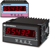
TDP-4921/TDP-4931 |
RS-485 RS-232C Analog output Alarm output BCD output LINKSHIP support |
- 16bit analog output with 0.5ms update |
 |
SPD-4801 |
RS-485 Modbus CAN Analog output Alarm output Zero shift Span shift Count Stop/Start LINKSHIP support |
- 48x96 size speed/totalizer [switchable] for frequency meter, tachometer, flowmeter, speed meter, totalizer, etc. |
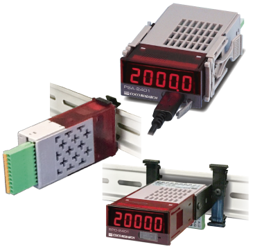 |
SPD-2401 SPDL-2401 |
RS-485 Modbus CAN Analog output Alarm output Zero shift Span shift Count Stop/Start LINKSHIP support |
- 24x48 size speed/totalizer [switchable] for frequency meter, tachometer, flowmeter, speed meter, totalizer, etc. |
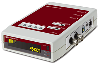 |
SPD-HD |
RS-485 Modbus CAN Analog output Alarm output Zero shift Span shift Count Stop/Start LINKSHIP support |
- Speed/totalizer [switchable] for frequency meter, tachometer, flowmeter, speed meter, totalizer, etc. |
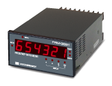
|
FRM-3921 |
RS-232C Alarm output 2ch Analog output BCD output RS-485 |
- Inputs signals from 2 channels and measures the speed ratio between the channels. |
