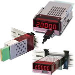
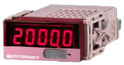
| Model |
SPDL-2401 / SPDL-2411 / SPDL-2431 / SPDL-2451 |
| Measuring method |
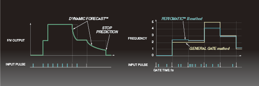
PeriomaticTM B method [Periodic arithmetic method] |
| Input |
| Number of input points |
1 |
| Input frequency |
0.0006Hz to 1.0MHz |
| Input resolution |
Approx. 10.4ns [96MHz] |
| Input Signal |
5V logic, zero cross, NPN open collector, 12V logic, input customized signal |
| Input method |
Single-phase signal, 2-phase signal [direction signal, UP/DOWN signal]
|
| General-purpose input type |
| Input Level and Sensitivity |
| 5V logic |
Trigger level 2.5V |
Hysteresis ±0.4V |
| Zero-cross |
Trigger level 0V |
Hysteresis ±0.03V |
| NPN open collector |
Trigger level 2.5V |
Hysteresis ±0.4V |
| 12V logic |
Trigger level 6V |
Hysteresis ±0.4V |
| Customized input |
Trigger level 0-9.0V Can be set in 10mV increments
Hysteresis[Small]±0.03V [Medium]±0.4V [Large]±1.3V, trigger level 4.7V or lower/ ±2.6V, trigger level 4.7V or higher |
|
| Input pulse |
[Small] [Medium] 0.2 μs or more [Large] 0.3 μs or more, for both H and L levels |
| Input resistance |
[5V logic] [zero cross] [NPN open collector] [Input customized signal, trigger level 4.7V or lower] 10kΩ
[12V logic] [input customized signal, trigger level 4.71V or higher] 5kΩ |
| Input withstand voltage |
±30V *Inputs and outputs are not insulated for the general-purpose input option.
|
| Line driver input Option |
| Input signal |
Line driver signal |
| Input withstand voltage |
±25V differential voltage |
| Recommended line driver |
Equivalent to AM26LS31 |
| Termination resistance |
300Ω [standard specification] *Input and output are isolated for the line driver input option.
|
| 2-Phase[A/B] input Option
Switchable between 1-phase and 2-phase [A/B] signals. When single-phase input is used, input level, Trigger level, etc. are the same as for 2-phase signals. |
| Input Level and Sensitivity |
| 5V logic |
Trigger level 2.5V |
|
| Zero-cross |
Trigger level 0V |
|
| NPN open collector |
Trigger level 2.5V |
|
| 12V logic |
Trigger level 6V |
|
| Customized input |
Trigger level 0V/2.5V/6V Hysteresis [Small]±0.03V, [Medium]±0.4V |
|
| Input pulse |
[Small/Medium] 0.2 μs or more, for both H and L levels |
| Input resistance |
10kΩ |
| Input withstand voltage |
±30V
|
| Common items for each input |
| Input low-pass filter |
Select from OFF, 500Hz, 5kHz, 120kHz, or 800kHz |
| Trigger edge |
Fall |
| Input connector |
Spring lock plug connector / [J04 option] M2 screw type plug connector |
| Sensor Power supply |
[Option] [H] DC +12V±5% 60mA max / [L] DC +5V±5% 150mA max
*When USB power is supplied, sensor power is not output.
|
| Calculation |
| Measurement mode |
Velocity meter/ Frequency meter/ Period meter [Seconds only] / Counter[Totalizer] |
| Calculation rate |
Set the reference pulse number, reference change, and speed unit time with respect to the input frequency |
| Frequency divider ratio |
1 to 60000 |
| Output moving average |
1 to 99 |
| Dynamic PredictiveTM |
8 levels [including continuous and stop prediction] |
| Control input |
None or 1 point [depending on model] [D2] Option to add 2 points. |
| [Setting contents] |
Set a function for each control input and control from outside |
| Functions |
Hold [current/max./min. value, max. fluctuation range], Zero/Span shift [count], Stop/Start count |
| ON logic |
Normally open / Normally closed |
| [Operation Method] |
ON when control input pin [ON logic] is shorted [open] to GND; setting is reflected when open [shorted] |
| [Data communication] |
Command control is possible via communication [USB, CAN, RS-485]
Commands set via communication cannot be released by terminal input. Reset execution is always required. |
| Low cut |
Low cut function Stop judgment at a speed lower than the set value
|
| Display |
| Display Color |
Red LED |
| Indicator [Numerical Display] |
5-digit, 7-segment LED Character height 9mm / Display range:-19999 to 99999
Polarity indication: Reverse rotation -Lighted / Over indication: OL / Zero indication: Leading zero suppress |
| Decimal point position |
Semi-fixed Decimal point position is set in program mode. [0] *****, [1] ****.* to [4] *.**** |
| Display update time |
0.3 sec [settable from 0.1 to 9.9 sec] |
| Display accuracy |
20ppm ± 1 digit |
| Indicator [3 round LEDs] |
LED 1 point [selected from power/ control input/ trigger/ comparator output]
|
| USB communication |
| Communication specification |
USB2.0 [Serial port communication by USB virtual COM 230.4kbps] |
| Communication function |
Writing/reading of set values/ Continuous output of measured values |
| Output update time |
40 to 9999.9ms, settable in 0.1ms increments
|
| General Information |
| Operating temp./humidity |
-10°C to +50°C / 35 to 85%RH [non-condensing] |
| Power supply voltage |
7 to 30V DC with reverse connection protection. Power supply from USB host: 5V |
| Power consumption |
3W or less |
| Isolation |
Power Supply/ Other Input/Output |
| Withstand voltage |
Power supply/ Other input/output: 500V DC between each terminal for 1 minute |
| Weight |
Approx. 60g
|
| CAN Option |
| Communication specifications |
CAN2.0B 10 k / 20 k / 50 k / 100 k / 250 k / 500 k / 1M bps [Format] INTEL/MOTOROLA, [Frame] 11bit/29bit |
| Communication function |
Writing/reading of set values/ Continuous output of measured values |
| Setting item |
CAN transmit ID, CAN receive ID |
| Output update time |
40ms to 9999.9ms settable in 0.1 ms increment
|
| RS-485 communication option Modbus RTU support is available upon request. |
| Number of connected units |
32 units [max.] |
| Communication format |
2-wire multi-drop serial communication |
| Communication method |
Asynchronous |
| Communication standard |
RS-485 |
| Communication speed |
9600bps / 19200bps / 38400bps Set in program mode |
| Data format |
Start bit: 1 bit / Stop bit: 1 bit / Data length: 8 bits / Parity bit: None |
| Communication code |
ASCII |
| Communication function |
Writing/reading set values/measurement value output [response to request command]
|
| Analog output option |
| Output signals |
[E1] 0 - 10V [E5] 0 - 5V [R1] ±10V [R5] ±5V [I1] 4 - 20mA [Select a model] |
| D/A conversion method |
DAC conversion method |
| Output resolution |
16bit16bit [50,000 or more] |
| Load resistance |
[Voltage output] 4.7kΩ or more / [Current output] 300Ω or less |
| Output accuracy |
[Voltage output] ±0.1% of FS @ 23℃/ [Current output] ±0.1% of FS @ 23℃ |
| Temperature fluctuation |
±200ppm/℃ or less |
| Output scaling |
Arbitrary scaling is possible by full scale and zero scale settings |
| Output update time |
40 to 9999.9ms settable in 0.1ms increments |
| Input/output delay time |
Output update time + analog rise time 150 μs max.
|
| Alarm [Comparator] output option |
| Setting method |
Set in program mode |
| Number of outputs |
2 points (or 1 point) depends on the models 1 point for line driver input and analog output with comparator output specification. |
| Output form |
Isolated non-contact output [photo-MOS relay] No polarity.
When comparator operating condition is ON, resistance between COMP and COM
50 Ω or less for C2 option [2 comparator] / 100 Ω or less for C1 option [1 comparator] |
| Output load voltage |
Peak AC/DC280V 100mA [resistive load] / ON resistance 50Ω or less |
| Output logic |
Comparison is made with polarity [0 is greater than minus]
| [Over] |
ON when set value or more |
| [Under] |
ON when set value or less |
| [Within range] |
ON within the set value, OFF outside the range |
| [Out of range] |
ON outside the set value, OFF within the range |
|
| Update time |
Depends on analog output update time setting. Response time 1ms [max.] |