| No need for Complex settings |
| No need for Expensive CAN analyzers |
| No need for Expensive diagnostic equipment |
| CAN data input | |
Automobiles, construction machinery, agricultural machinery, office equipment, etc.    |
 |
| Conversion | ||
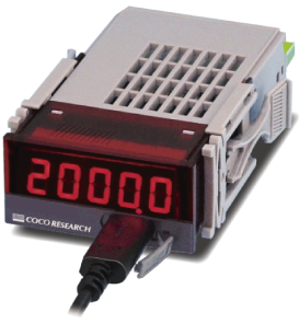
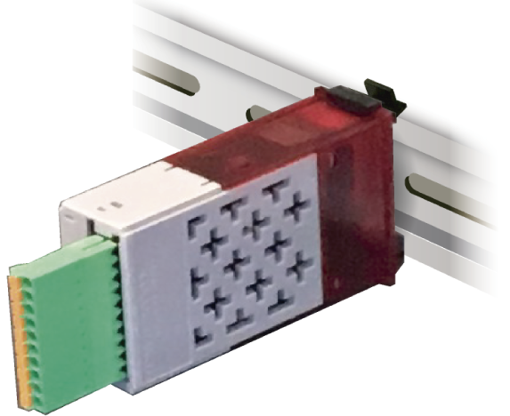
CAN-24 series 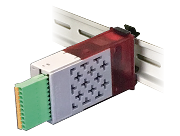 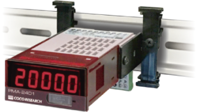 |
|
|
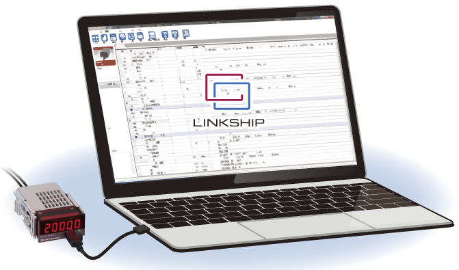
| Power supply ・7 to 60V DC ・USB power 5V |
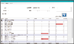
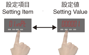
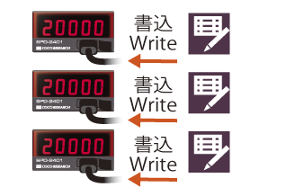
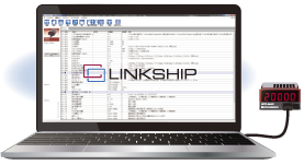
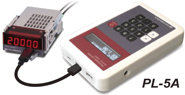
Setting ・LINKSHIP software ・Setting unit PL-5A |
|
| 16-bit analog output | |
| Check data with your equipment Easy acquisition of CAN signals |
|
Data loggers |
Oscilloscopes, etc. |
| CAN data input | |
| Specific CAN signals |
|
| Conversion | ||
| CAN-24 series |
|
|
| Power supply ・7 to 60V DC ・USB power 5V |
Setting ・LINKSHIP software ・Setting unit PL-5A |
|
| Alarm output | |||
| Relay ON | External power source  |
Voltage application |
Relay |
| PLCs, indicator lights, etc. |
  |
||
| Applications list> |
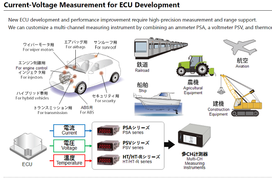
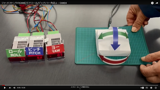
Monitoring of In-Vehicle ECUs
| >View more |
Pinpoint check of any CAN signal
| >View more |

Wind Tunnel Testing / vehicles, motorcycles, architectural and civil engineering structures, etc.
| >View more |
| >View more |
BPS: 10k, 20k, 50k, 100k, 250k, 500k, 1Mbps
FORMAT: INTEL (Little Endian) /MOTOROLA (Big Endian)
FRAME: Standard, 11bit length ID / Extended. 29bit length ID
Upper 5-bit mask function: Enables reception detection excluding the upper 5 bits of extended (29-bit length ID) data.
Interruption detection function (CAN bus line monitoring): Displays OFF when CAN bus data reception is interrupted.
If equipped with an alarm output option, alarm output is also possible. Detection time can be set from 1s to 999s.
| See 40ms type> |
| See Low-cost version > |
| LINKSHIP Page > |
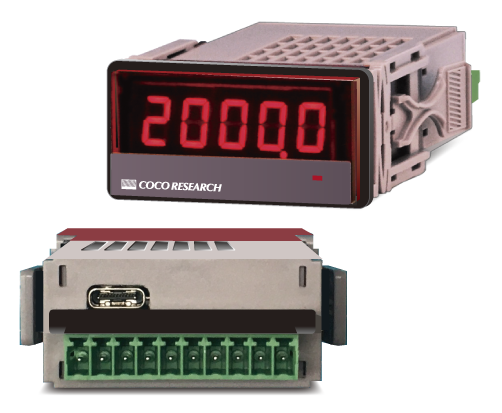
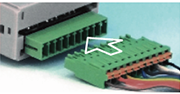
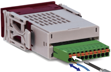
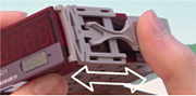
Detachable Plug Connectors
Simply connect the wires to the connector and plug it in by hand.
Detachable Plug Connectors
Spring lock type [Standard]
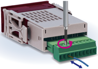
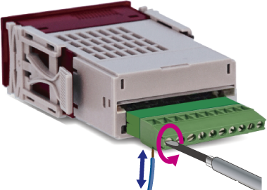
Detachable Plug Connectors
M2 screw type [Option]
Fixed Connector
Non-detachable [Customize]
Mounting hooks
Fixing the main body
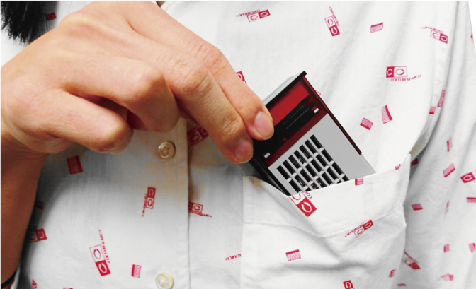
Carry PC, instrument, and cable, and measure with USB power supply. Storage case BXS-1 is also available.
 |
  >BXS-1 Overview |
One-touch fixture and display-less type
 |
 |
|
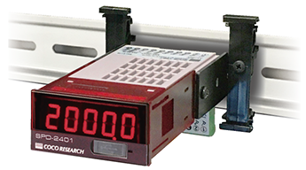
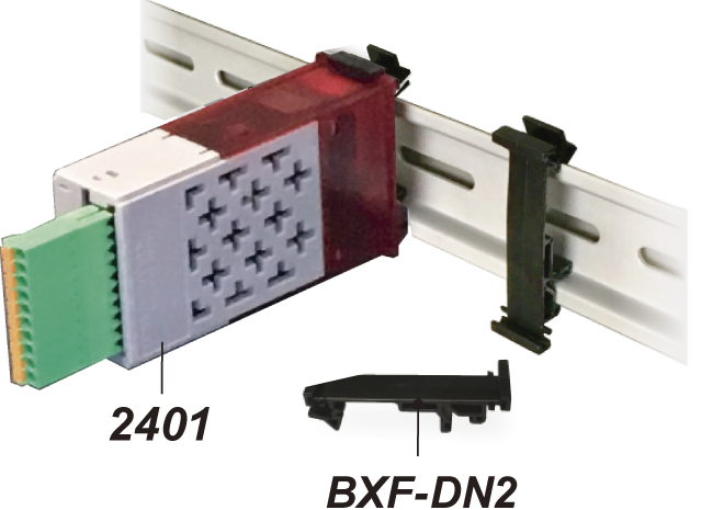
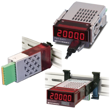
| BXF-DN2 DIN rail attachment [sold separately] |
CAN-2451 Display-less type |
CAN-2431 With display type |
| >BXF-DN2 page |
| Model List and Options > |
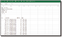
| Name | CAN to analog converter | ||||||||
| Model | CAN-2401 / CAN-2411 / CAN-2431 / CAN-2451 | ||||||||
| Input | |||||||||
| Number of input | 1 point [Communication standard] CAN2.0B | ||||||||
| CAN BPS | Set from 10k / 20k / 50k / 100k / 250k / 500k / 1M bps | ||||||||
| CAN FORMAT | Select from INTEL (Little Endian) / MOTOROLA (Big Endian) | ||||||||
| CAN FRAME | Select from Standard (11bit length ID) / Extended (29bit length ID) | ||||||||
| Extended ID Upper 5-bit Mask | Upper 5-bit mask setting function for Extended ID (29 bits), reception determination excluding upper 5 bits | ||||||||
| Received Data Format | Configurable from FLOAT, DOUBLE, U32, S32, U16, S16, U8, S8, 1bit | ||||||||
| Data Frame | Configures the start byte for reading 8-byte (DLC8) received data | ||||||||
| Bit Reception | Bit Array (Numbering) Reception of 1-bit data from 0 to 63 bits (specifies read byte and bit position) | ||||||||
| Data Disconnection Detection | A function to detect when data reception has been interrupted. The data reception interval time can be set in units of 1s to 999s. The disconnection detection can be set to trigger an alarm output using COM1. (Outputs when the disconnection detection time elapses) |
||||||||
| Input connector | Plug type [Standard] Spring lock / [Option] M2 screw | ||||||||
| Calculation | |||||||||
| Measurement Unit | CAN Integer Data / Point-to-Point Rate | ||||||||
| Setting Value Memory | Non-volatile Memory (EEPROM) | ||||||||
| Display | |||||||||
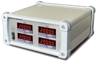
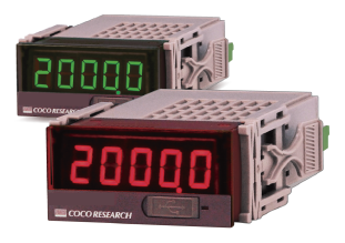
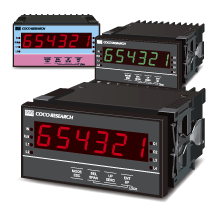
| Display Color | [Standard] CAN-2401 Red LED [Option] CAN-2401-G Green LED |
||||||||
| Indicator [Numerical Display] | 5-digit, 7-segment LED Character height 9mm Display range:-19999 to 99999 Over indication: OL / Zero indication: Leading zero suppress |
||||||||
| Decimal point position | Semi-fixed Set in program mode. [0] *****, [1] ****.* to [4] *.**** | ||||||||
| Display update time | 0.3 sec [settable from 0.1 to 9.9 sec] | ||||||||
| Display accuracy | 20ppm ± 1 digit | ||||||||
| Indicator | LED 1 point [power] | ||||||||
| USB communication | |||||||||
| Specification | USB2.0 [Serial port communication by USB virtual COM 230.4kbps] | ||||||||
| Function | Writing/reading of set values/ Continuous output of measured values | ||||||||
| Output update | 1 to 9999ms, settable in 1ms increments | ||||||||
| General Information | |||||||||
| Operating temp./humidity | -10°C to +50°C / 35 to 85%RH [non-condensing] | ||||||||
| Power supply | 7 to 60V DC with reverse connection protection. Power supply from USB host: 5V | ||||||||
| Power consumption | 3W or less | ||||||||
| Isolation | Power supply / Other input/output | ||||||||
| Withstand voltage | Between each terminal of the above isolation: DC 500V for 1 minute |
||||||||
| Weight | Approx. 60g | ||||||||
| Analog output option | |||||||||
| Output signals | [E1] 0 - 10V [E5] 0 - 5V [R1] ±10V [R5] ±5V [I1] 4 - 20mA [Select a model] | ||||||||
| D/A conversion | DAC conversion method | ||||||||
| Output resolution | 16bit [50,000 or more] | ||||||||
| Load resistance | [Voltage output] 4.7kΩ or more / [Current output] 300Ω or less | ||||||||
| Output accuracy | [Voltage output] ±0.1% of FS @ 23℃/ [Current output] ±0.1% of FS @ 23℃ | ||||||||
| Temp. fluctuation | ±200ppm/℃ or less | ||||||||
| Output scaling | Arbitrary scaling is possible by full scale and zero scale settings | ||||||||
| Output update | 1 to 9999ms settable in 1ms increments | ||||||||
| Input/output delay | Output update time + analog rise time 150 μs max. | ||||||||
| Alarm [Comparator] output option | |||||||||
| Setting method | Set in program mode | ||||||||
| Number of outputs | 2 / 4 points [depends on the models] | ||||||||
| Output form | Isolated non-contact output [photo-MOS relay] No polarity. When comparator operating condition is ON, resistance between COMP and COM 50 Ω or less |
||||||||
| Output load voltage | Peak AC/DC280V 100mA [resistive load] / ON resistance 50Ω or less | ||||||||
| Output logic | Comparison is made with polarity [0 is greater than minus]
|
||||||||
| Update time | Depends on analog output update time setting. Response time 1ms [max.] | ||||||||
| View List > |
| Load cell/Pressure/Strain | CAN to analog |
| DC current | DC voltage |
| Thermocouple meter | Thermistor meter |
| RTD meter | Resistance Meter |
| Speed/Count, Pulse Freq. | Torque/Freq.deviation |
Various Outputs
Software LINKSHIP
For data logging, setting
Customization
EX48
EX(L)24