*1: Outputs are optional (USB is standard only)
・Supports frequency pulse signal input. Sensor power supply output option available.
・Trigger level adjustable from 0 to 9.00V. Compatible with various sensors.
・Input/output values can be scaled independently for each channel.
・Analog output: Up to 0.1ms refresh rate.
・CAN output: Up to 1ms refresh rate.
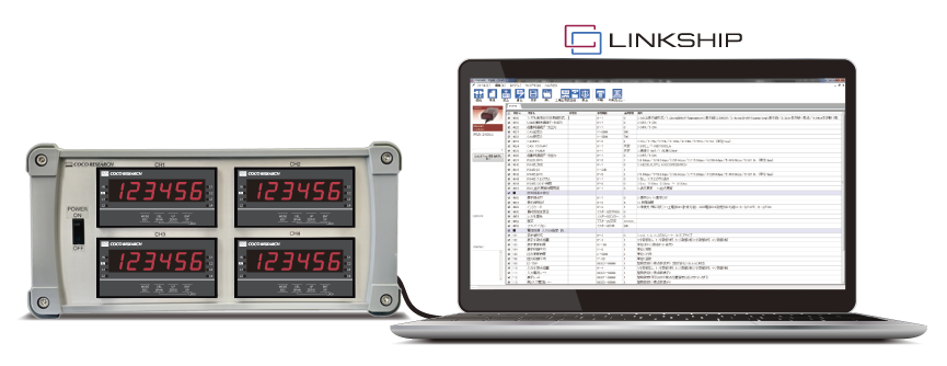
・Easy configuration for 4 units using the dedicated free software LINKSHIP.
・Can be used for position, angle, totalization, and counter applications by switching settings.
・Calibration as a boxed unit and document issuance are also available.*2
*2: In some cases, calibration documents cannot be issued.
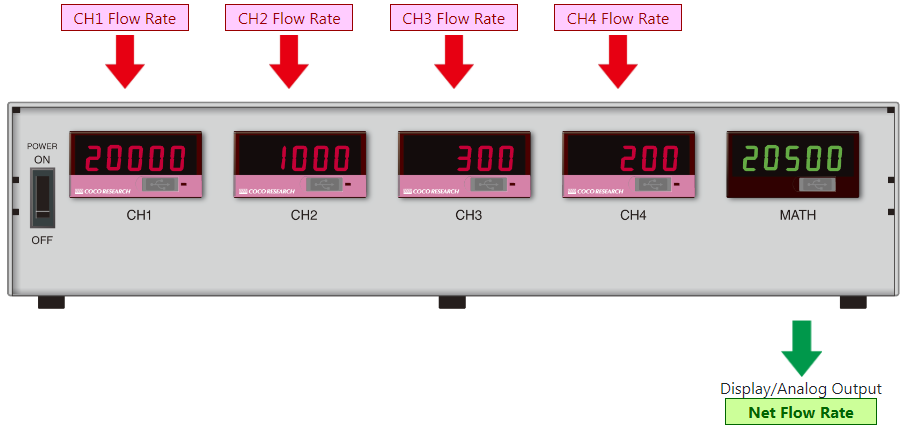
SPD-4801 (48x96 size) 4-Unit Type
[Inquiry No.] 1065 [Dimensions] W300 H140 D93* |
SPD-2401 (24x48 size) 4-Unit Type
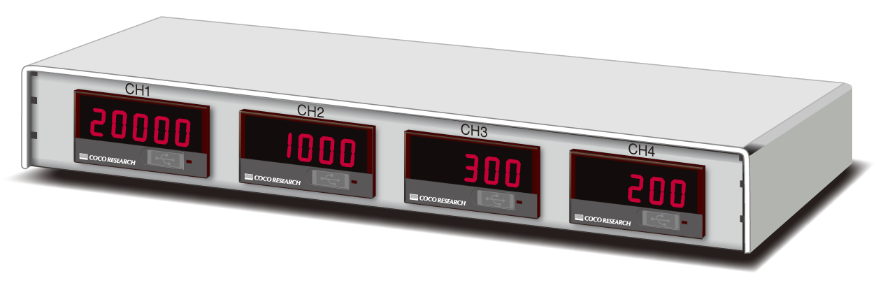 [Inquiry No.] 1028 [Dimensions] W257 H35 D84* |
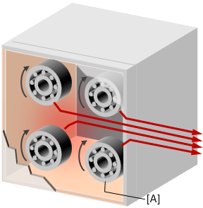
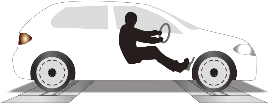
Individual rotational speed measurement of automotive 4-wheels
Measurement Image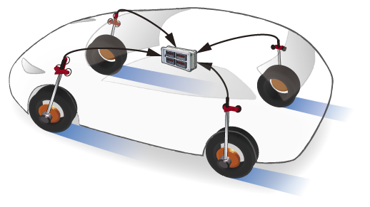
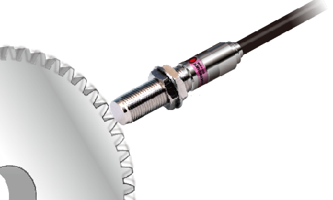
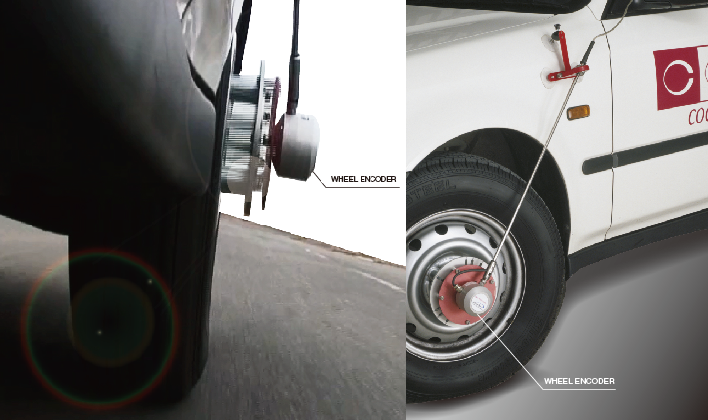
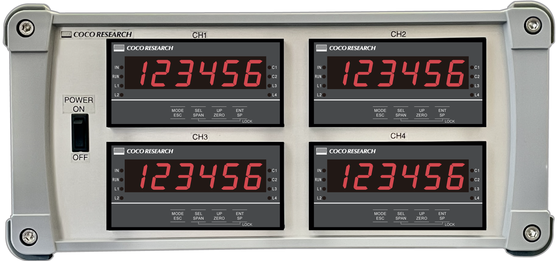
Wheel encoders (automotive driving test system) are attached to 4 wheels and output to the 4CH Tachometer.
CH1 / LF (Front Left)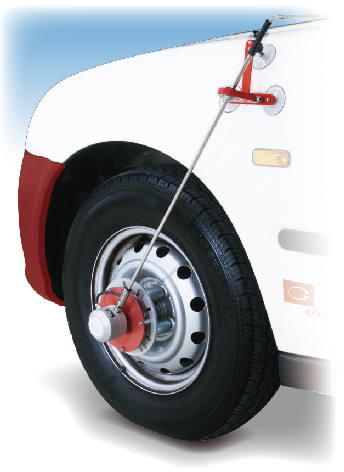 |
CH2 / RF (Front Right)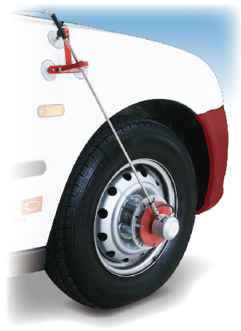 |
CH3 / LR (Rear Left)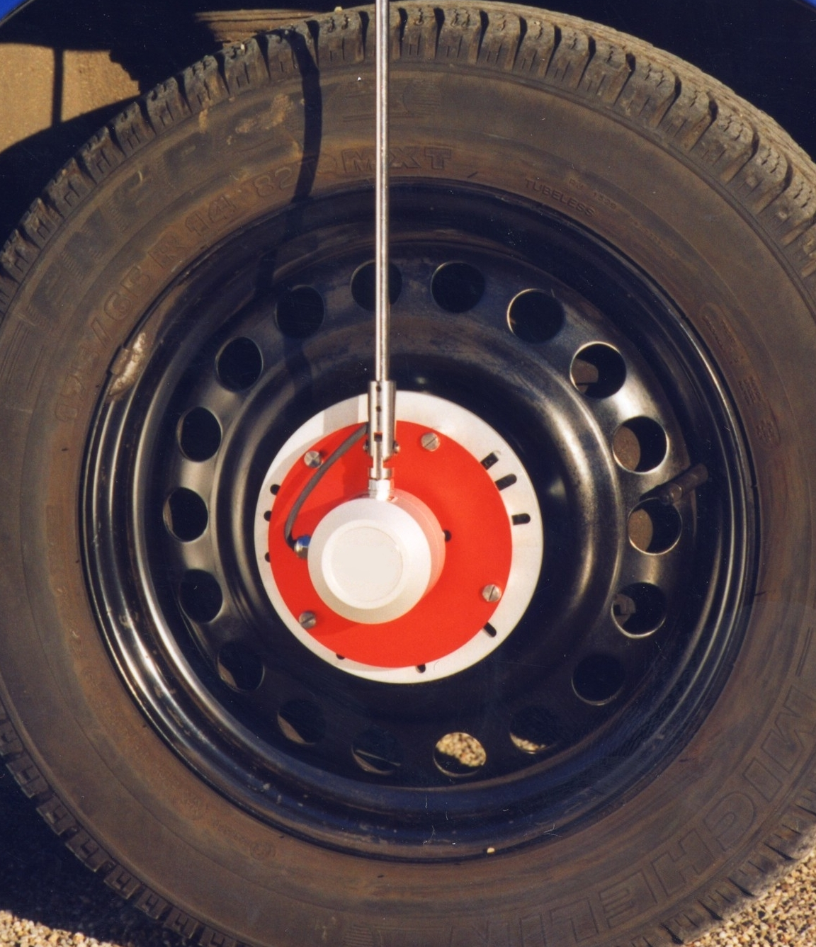 |
CH4 / RR (Rear Right)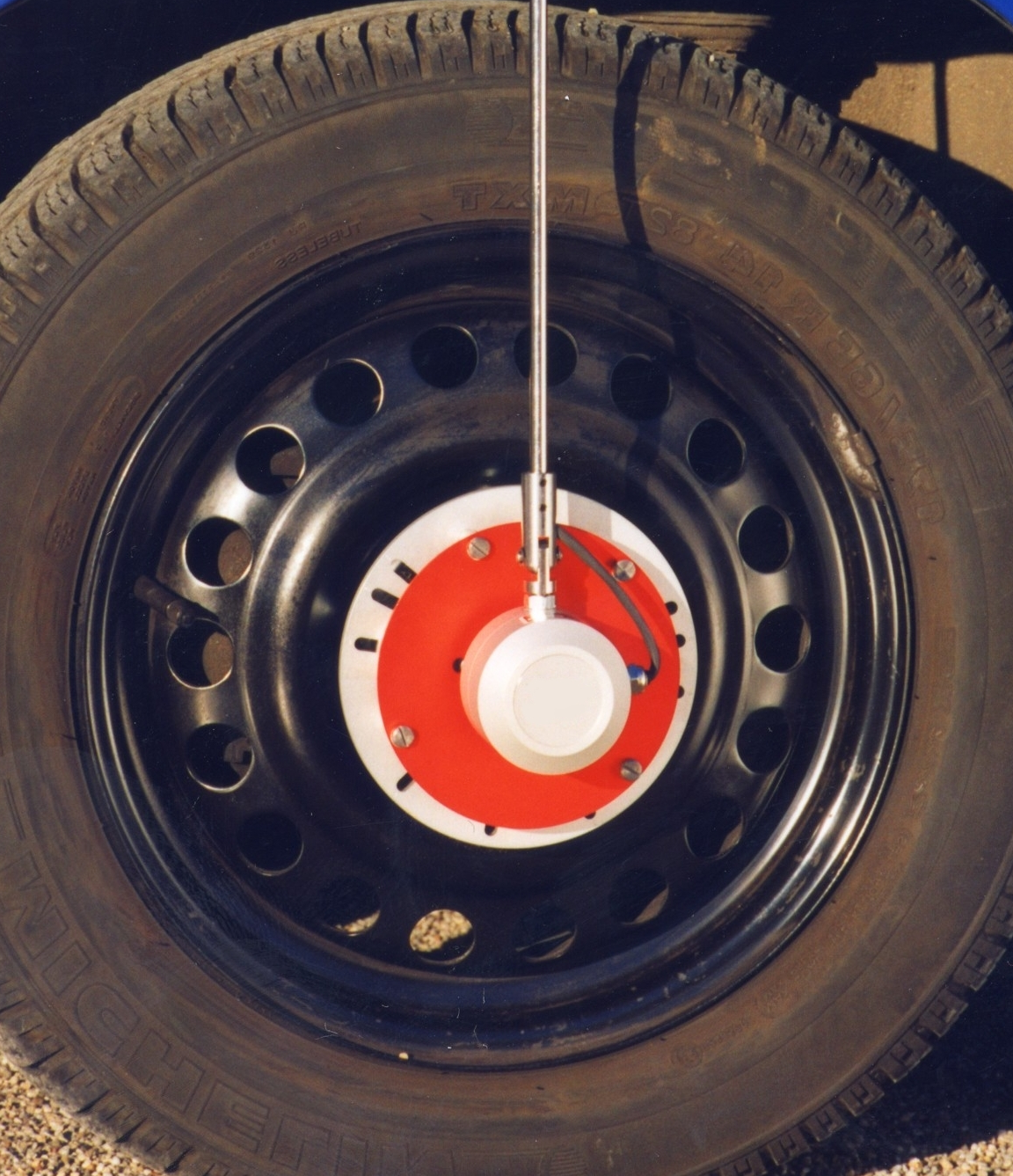 |
|||||
|
|
|
|
|||||
 |
|
|
|
 |
 |
4CH Output CANAnalog Alarm RS-485 USB Ethernet etc. |
Fluid flow rate for each of the 4 wheels
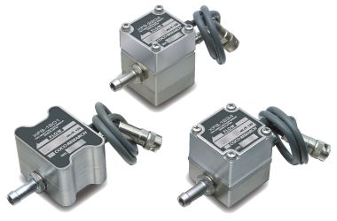
Behavior and hydraulic oil flow at multiple locations
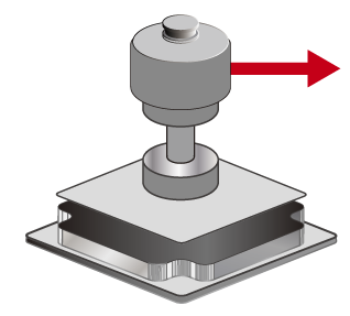
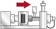
Flow rates across multiple pathways for fuel, lubricants, etc.
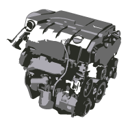
For monitoring liquid flow rate and rotation
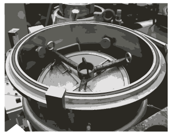
| Please consult us |
| Speed [Frequency Pulse] |
| Torque [Frequency Pulse] |
| Flow Rate / Velocity |
| Angle, Position, Displacement, Totalization |
| Current |
| Voltage |
| Temperature |
| Resistance |
Significantly reduces wiring compared to BCD via 3-wire system.
Strong error detection system resists noise and improves safety.
| SAE J1939 (DLC 8 bytes or less) Customization Examples Available Please contact us for other types of customization. |
RS-485, Ethernet*1 (LAN) [Optional]
*1: Ethernet is supported on SPD-4801 only
USB Type-C 1ms Refresh [Standard] Data Logging & Configuration
Resolution over 50,000, Full/Zero scale settings, Analog output zero adjustment
Dual Analog Outputs [Optional]
Dual analog outputs are available. Example: 0-10V and 4-20mA output
Alarm Output 1ms Refresh [Optional] 1 to 4 points
| 5V Logic |
| Zero Cross |
| NPN Open Collector |
| 12V Logic |
| Customized Signal |
| Input Isolation |
| Phase A/B Input |
| Line Driver |
| Trigger Level 0-9.99V |
| Hysteresis |
| Pull-up ON/OFF |
| 5V |
| 12V |
| Other Voltages |
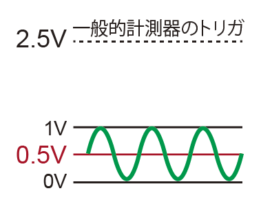
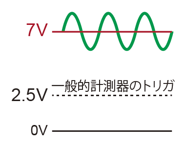
| Versatile Trigger Levels (Thresholds)
While 2.5V is common for general measuring instruments, the SPD allows configuration from 0 to 9V in 10mV steps.
|
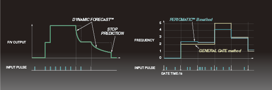
| What is PeriomaticTM? |
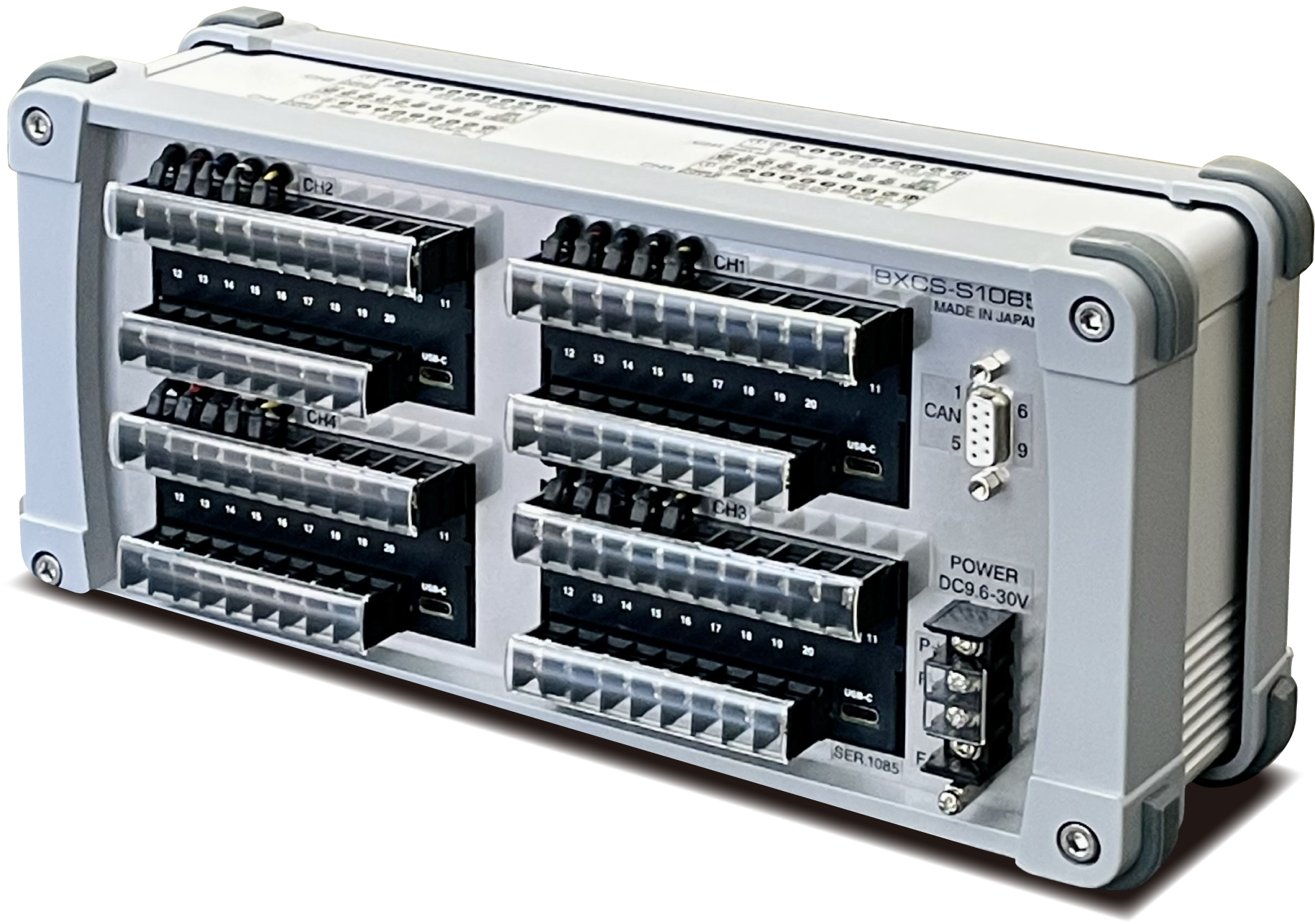
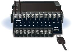
Rear: Equipped with a USB-C port for each channel
Prevents manual entry errors, reduces management effort and cost
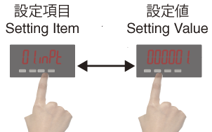
Configure and check on PC screen. Prevents physical button errors
Simply copy and write the master settings even for multiple units
SPD-4801 (48x96 size) 4-Unit Type 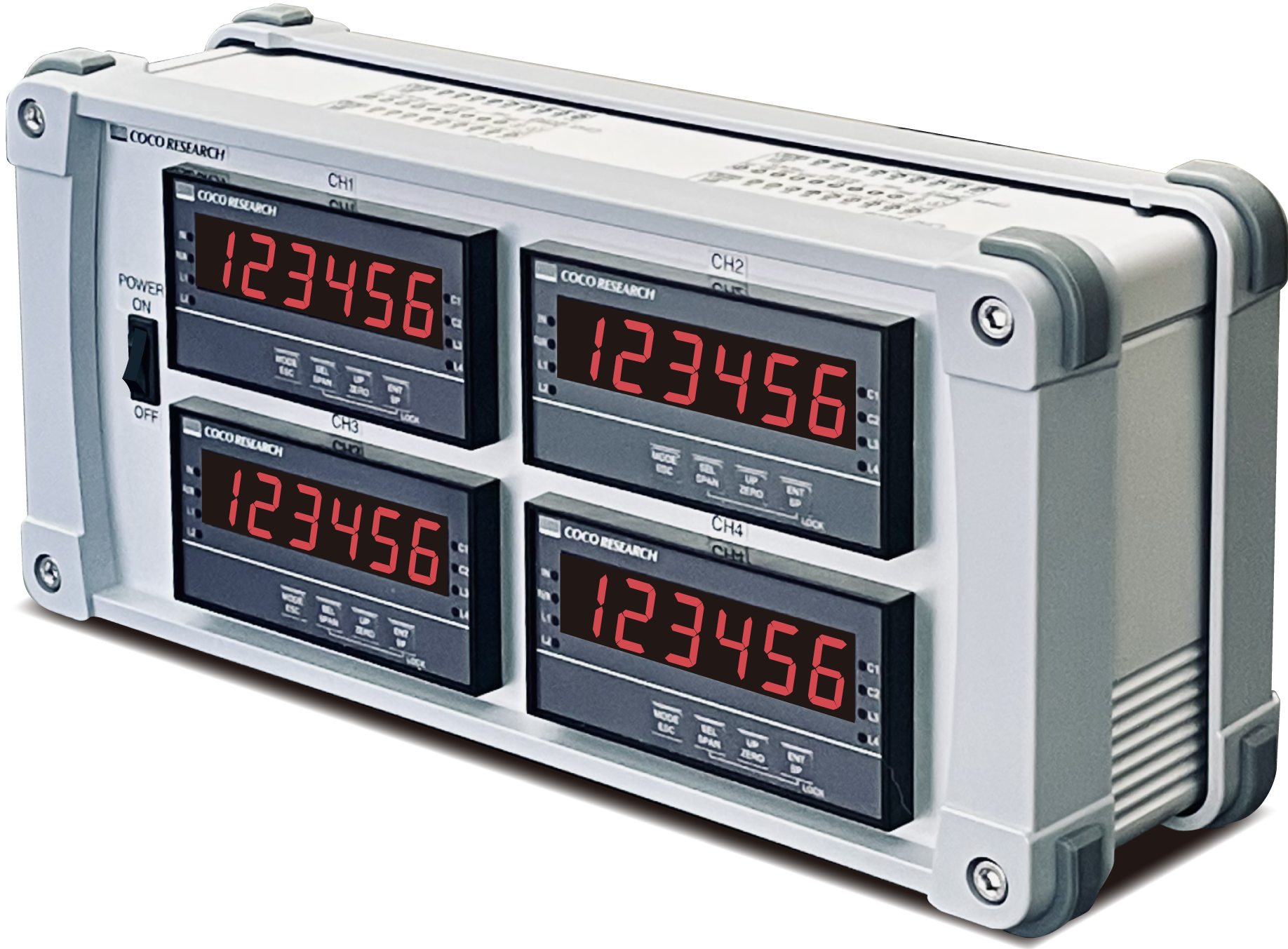 |
SPD-24 / SPDL-24 (24x48 size) 4-Unit Type 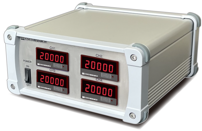 *For SPDL-24 4-unit type, the lower part of the display is pink |
SPD-24 / SPDL-24 4-Unit Type 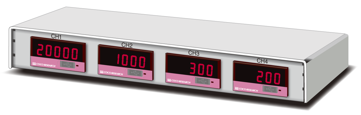 |
Common Features
・Simultaneous output of 16-bit analog and CAN is possible [Optional]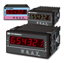
48x96 Size
Analog Output 0.1-9999.9ms refresh
Digital Comms 1-9999ms refresh
Power Supply AC100-240 / DC9.6-30V
Display 6 digits (Green LED version also available)
Panel Dimensions W96, H48
Front Configuration Buttons
| Go to Product Page > |
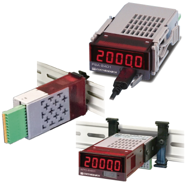
24x48 Size
Analog Output 0.1-9999.9ms refresh
Digital Comms 1-9999ms refresh
Power Supply DC7-60V / USB power supply 5V
Display 5 digits (Green LED version also available)
Panel Dimensions W48, H24
| Go to Product Page > |
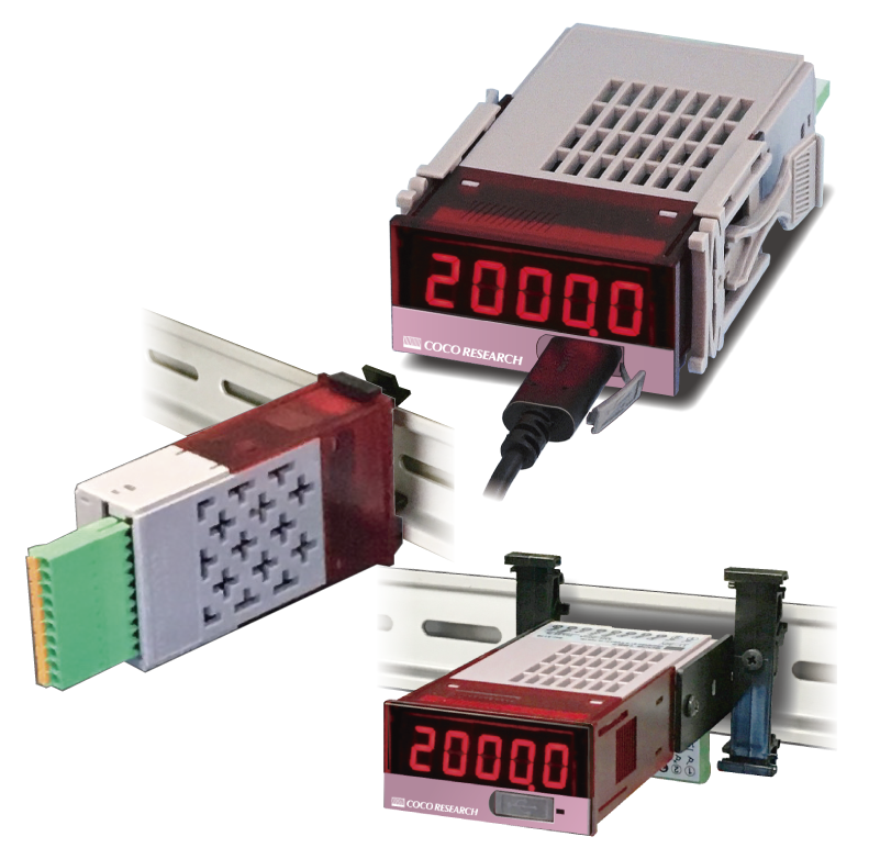
24x48 Size [Low-Cost Model]
Analog Output 40-9999ms refresh
Digital Comms 40-9999ms refresh
Power Supply DC7-30V / USB power supply 5V
Display 5 digits (Red LED only)
Panel Dimensions W48, H24
| Go to Product Page > |
| Model | SPD-4801 | ||||||||||||||||||
| Measurement System | PeriomaticTM B (Cycle Calculation) System | ||||||||||||||||||
| Input Section | |||||||||||||||||||
| Number of Inputs | 1 point | ||||||||||||||||||
| Input Range | 0.0006Hz - 1.0MHz | ||||||||||||||||||
| Input Resolution | Approx. 10.4ns (96MHz) | ||||||||||||||||||
| Input Signal | 5V Logic, Zero Cross, NPN Open Collector, 12V Logic, Customized Input Signal | ||||||||||||||||||
| Input System | Single-phase signal, 2-phase signal (Direction signal, UP/DOWN signal) | ||||||||||||||||||
| General-Purpose Input Type | |||||||||||||||||||
| Input Level / Sensitivity |
|
||||||||||||||||||
| Input Pulse | 0.2μs or more (Small/Medium hysteresis) / 0.3μs or more (Large hysteresis) for both H and L levels | ||||||||||||||||||
| Input Resistance | 5kΩ: 12V Logic, Customized Input Signal (Trigger level 4.71V or more) 10kΩ: Other than the above |
||||||||||||||||||
| Input Dielectric Strength | ±30V *For General-Purpose Input Type, input and output are non-isolated. |
||||||||||||||||||
| Line Driver Input Type (Optional) | |||||||||||||||||||
| Input Signal | Line driver signal | ||||||||||||||||||
| Input Dielectric Strength | ±25V (Differential voltage) | ||||||||||||||||||
| Recommended Line Driver | AM26LS31 equivalent | ||||||||||||||||||
| Terminating Resistor | 300Ω (Standard spec) *For Line Driver Input Type, input and output are isolated. |
||||||||||||||||||
| 2-Phase (A/B Phase) Input Type (Optional) Switchable between single-phase and 2-phase (A/B) signals. For single-phase input, the input level, trigger level, etc., comply with the 2-phase signal specifications. | |||||||||||||||||||
| Input Level / Sensitivity |
|
||||||||||||||||||
| Input Pulse | 0.2μs or more for both H and L levels | ||||||||||||||||||
| Input Resistance | 10kΩ | ||||||||||||||||||
| Input Dielectric Strength | ±30V | ||||||||||||||||||
| Common Items for Each Input | |||||||||||||||||||
| Input Low-Pass Filter | OFF / 500Hz / 5kHz / 120kHz / 800kHz | ||||||||||||||||||
| Trigger | Falling edge | ||||||||||||||||||
| Connector | Terminal block 7.62mm pitch, M3 free-terminal screws | ||||||||||||||||||
| Sensor Power Supply Output | Optional: [H] DC +12V±5% 60mA max / [L] DC +5V±5% 150mA max | ||||||||||||||||||
| Calculation Section | |||||||||||||||||||
| Measurement Mode | Tachometer / Frequency Meter / Cycle Meter (seconds only) / Totalizer [Switchable] | ||||||||||||||||||
| Calculation Rate | Sets the reference number of pulses, reference change amount, and speed unit time relative to the input frequency. | ||||||||||||||||||
| Frequency Division Ratio | 1 - 60000 | ||||||||||||||||||
| Moving Average | 1 - 99 | ||||||||||||||||||
| Dynamic PredictionTM | 8 levels (including continuous prediction and stop prediction) | ||||||||||||||||||
| Control Input | None or 1 point (depending on the model) | 2 points can be added with the [D2] option | ||||||||||||||||||
| (Settings) | Functions are configured for each control input (CTL) and controlled externally. [Functions] Hold (Current, Maximum, Minimum, Max Peak-to-Peak values), Zero Shift (Totalization), Span Shift (Totalization), Totalization Stop, Start [ON Logic] Normally Open, Normally Closed |
||||||||||||||||||
| (Operation) | Short-circuiting (or opening) the control input (CTL*) terminal (ON logic) to GND reflects the configured settings. | ||||||||||||||||||
| (Data Comms) | Command control via communications is supported (USB, CAN, RS-485) *Commands set via communication cannot be cleared by terminal inputs. A reset execution is required. | ||||||||||||||||||
| Low-Cut | Determines full stop at speeds below the set value. | ||||||||||||||||||
| Display Section | |||||||||||||||||||
| Display (Numeric) | 6 digits, 7-segment LED, Character Height: 14.2mm, Red / [G] Green LED (Optional) Display Range: -199999 to 999999 Polarity Display: "-" lights up during reverse rotation Overflow Display: OL | Zero Display: Leading zero suppression Display Refresh: 0.3 seconds (Configurable from 0.1 to 9.9 seconds) Display Accuracy: 20ppm±1 digit |
||||||||||||||||||
| Decimal Point Position | Semi-fixed, configured in program mode | 0: □□□□□□ | 1: □□□□□.□ to 4: □□.□□□□ | ||||||||||||||||||
| Indicators 4 Round LEDs |
[IN] Lights up during input operation | [RUN] Lights up when function setting is ON [COMP1][COMP2] Lights up when comparator output is ON (Optional) |
||||||||||||||||||
| USB Communication Section | |||||||||||||||||||
| Comms Specs | USB2.0 (Serial port communication via USB virtual COM, 230.4kbps) | ||||||||||||||||||
| Comms Functions | Writing/Reading of set values / Continuous output of measured values | ||||||||||||||||||
| Output Refresh | 1ms - 9999.9ms, configurable in 0.1ms steps | ||||||||||||||||||
| General Specifications | |||||||||||||||||||
| Operating Temp/Humidity | -10°C to +50°C, 35 to 85%RH, non-condensing | ||||||||||||||||||
| Power Supply Voltage [Select Model] |
[AF] AC100-240V (Maximum rating: AC85-264V) 50/60Hz [DF] DC9.6-30V (Maximum rating: DC9-36V) with reverse connection protection |
||||||||||||||||||
| Power Consumption | 3W or less | ||||||||||||||||||
| Isolation | Power supply / Other inputs and outputs | ||||||||||||||||||
| Dielectric Strength | Between each terminal listed above: DC500V for 1 minute | ||||||||||||||||||
| Weight | Approx. 340g | ||||||||||||||||||
| CAN Option | |||||||||||||||||||
| Comms Specs | CAN2.0B 10k / 20k / 50k / 100k / 250k / 500k / 1M bps Format (Intel/Motorola), Frame (11bit/29bit) |
||||||||||||||||||
| Comms Functions | Writing/Reading of set values / Continuous output of measured values | ||||||||||||||||||
| Setting Items | CAN Transmit ID, CAN Receive ID | ||||||||||||||||||
| Output Refresh | 1 - 9999.9ms, configurable in 0.1ms steps | ||||||||||||||||||
| RS-485 Option Please consult us for Modbus RTU support as well. | |||||||||||||||||||
| Max Connections | 32 units (max) | ||||||||||||||||||
| Comms Format | 2-wire multi-drop serial communication | ||||||||||||||||||
| Comms System | Asynchronous | ||||||||||||||||||
| Comms Standard | RS-485 | ||||||||||||||||||
| Baud Rate | 9600 / 19200 / 38400bps, configured in program mode | ||||||||||||||||||
| Data Format | Start bit: 1bit / Stop bit: 1bit / Data length: 8bit / Parity bit: None | ||||||||||||||||||
| Comms Code | ASCII | ||||||||||||||||||
| Comms Functions | Writing/Reading of set values / Output of measured values (responds to request commands) | ||||||||||||||||||
| Analog Output Option | |||||||||||||||||||
| Output Signal 【Select Model】 |
[E1] 0 - 10V | [E5] 0 - 5V | [R1] ±10V | [R5] ±5V | [I1] 4 - 20mA | ||||||||||||||||||
| D/A Conversion System | DAC conversion system | ||||||||||||||||||
| Output Resolution | 16bit (50,000 or more) | ||||||||||||||||||
| Load Resistance | Voltage output: 4.7kΩ or more | Current output: 300Ω or less | ||||||||||||||||||
| Output Accuracy | Voltage output: ±0.1% of FS @23°C | Current output: ±0.1% of FS @23°C | ||||||||||||||||||
| Temperature Fluctuation | ±200ppm/°C or less | ||||||||||||||||||
| Output Scaling | Arbitrary scaling is possible via full-scale and zero-scale configuration | ||||||||||||||||||
| Output Refresh | 0.1 - 9999.9ms, configurable in 0.1ms steps | ||||||||||||||||||
| I/O Delay Time | Output refresh time + Analog rise time: 150μs or less | ||||||||||||||||||
| Comparator (Alarm) Output Option | |||||||||||||||||||
| Configuration Method | Configured in program mode | ||||||||||||||||||
| Number of Outputs | 0 - 4 points, depending on model selection criteria (1 point for line driver input with comparator type analog output section) | ||||||||||||||||||
| Output Form | Isolated solid-state output (PhotoMOS relay), non-polar When comparator operating condition is ON, resistance between COMP-COM is: [C2](2 points) 50Ω or less / [C1](1 point) 100Ω or less |
||||||||||||||||||
| Load Voltage | Peak AC/DC280V 100mA (resistive load), ON resistance: Max 50Ω or less | ||||||||||||||||||
| Output Logic | Compared with polarity (0 is greater than minus)
|
||||||||||||||||||
| Refresh Time | Depends on the analog output refresh time setting / Response time: 1ms (max) | ||||||||||||||||||
| Ethernet Communication Option | |||||||||||||||||||
| Connector | RJ-45 (Network Interface) Lantronix XPort | ||||||||||||||||||
| Interface | 100BASE-TX / 10BASE-T (Auto-negotiation) Transmission Speed Standard: Category 5 / Category 4 |
||||||||||||||||||
| Comms Specs | Protocol: TCP/IP, Telnet communication connection | ||||||||||||||||||
| Output Refresh | Complies with USB communication: 1 - 9999ms | ||||||||||||||||||
| Transmission Compatibility | DIX Ethernet Version 2.0, IEEE 802.3 | ||||||||||||||||||
| LED Indicator | 100BASE-TX / 10BASE-T | ||||||||||||||||||
| Link/Activity Indicator | Full-duplex / Half-duplex (Telnet cannot handle networks encrypted with SSL/TLS, SSH, etc.) | ||||||||||||||||||
| Load Cell / Pressure / Strain | CAN Conversion |
| DC Current | DC Voltage |
| Thermocouple (Temp) | Thermistor (Temp) |
| RTD (Temp) | Resistance |
| Speed / Totalization | Frequency Deviation / Torque |
| View Lineup > |
- CAN & 16-bit Analog (Voltage/Current) Output
- USB-C: Configuration & Data Logging
- Alarm Output / RS-485
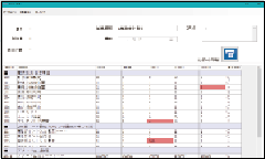
- Dedicated Software (Free): Settings Management, Report Printing, Data Logging
EX48 Series
EX(L)24 Series