| Model |
PSA-2401 / PSA-2411 / PSA-2431 / PSA-2451 |
| Input Signal |
DC Current Signal |
| Operation Method |
ΔΣ (Delta-Sigma) Integration Method |
| Input Section |
| Number of Inputs |
1 point |
Measurement Range
| Type |
Current Measurement Range |
Terminal Withstand Voltage |
Measurement Resolution |
| ±10A |
-10000.0 to +10000.0mA |
-11 to +11A |
0.5mA |
| ±5A |
-5000.0 to +5000.0mA |
-6 to +6A |
0.25mA |
| ±2A |
-2000.0 to +2000.0mA |
-3 to +3A |
0.1mA |
| ±1A |
-1000.0 to +1000.0mA |
-3 to +3A |
0.05mA |
| ±200mA |
-200.00 to +200.00mA |
-3 to +3A |
0.01mA |
| ±100mA |
-100.00 to +100.00mA |
-3 to +3A |
0.005mA |
| ±20mA |
-20.000 to +20.000mA |
-3 to +3A |
0.001mA |
| ±10mA |
-10.000 to +10.000mA |
-3 to +3A |
0.001mA |
| ±2mA |
-2.0000 to +2.0000mA |
-3 to +3A |
0.001mA |
| ±1mA |
-1.0000 to +1.0000mA |
-3 to +3A |
0.001mA |
| ±200μA |
-200.00 to +200.00μA |
-0.05 to +0.05A |
0.05μA |
| ±100μA |
-100.00 to +100.00μA |
-0.05 to +0.05A |
0.05μA |
| 4-20mA |
+4.0000 to +20.000mA |
0 to +3A |
0.001mA |
*Please consult us for other measurement ranges. |
| Measurement Accuracy |
±0.1% FS + 1 digit |
| Oversampling |
Fixed at 250kHz |
| Input Low-Pass Filter |
Cutoff Frequency: 1kHz |
| Sensor Power Output |
Option: [H] DC +12V±5% 60mA max / [L] DC +5V±5% 150mA max *No sensor power output during USB power supply.
|
| Calculation Section |
| Moving Average Count |
1 - 99 |
| Low-Cut |
Judged as 0 for current values below the set value. |
| Control Input |
None or 1 point (depending on the model) [D2] Option adds 2 points |
| (Settings Content) |
Configure functions for each control input (CTL) and control externally.
[Functions] Hold (Current value, Maximum value, Minimum value, Maximum fluctuation range value), Zero shift, Span shift, Zero set, Span set
[ON Logic] Normally Open, Normally Closed |
| (Operation Method) |
Short-circuit (open) the control input (CTL*) terminal (ON logic) to GND to turn ON; opening (short-circuiting) reflects the settings content. |
| (Data Communication) |
Command control via communication is possible (USB, CAN, RS-485) *Commands set via communication cannot be canceled via terminal input. Execution of a reset is strictly required. |
| Control Input Response Operation |
Response action can be configured (1ms to 1999ms) |
| Control Input Backup |
Enable/disable settings backup for shift and set operations (retains values even when powered OFF) |
| Setting Value Storage |
Non-volatile memory (EEPROM)
|
| Display Section |
| Display (Numerical Display) |
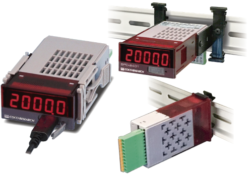
5-digit 7-segment LED, character height 9mm. PSA-2401: Red LED / PSA-2401-G: Green LED (Option)
Display Range: -19999 to 99999 | Polarity Display: "-" lights up during reverse rotation
Overflow Display: OL | Zero Display: Leading zero suppression
Display Update Time: 0.3 seconds (configurable within the range of 0.1 to 9.9 seconds) | Display Accuracy: 20ppm ± 1 digit @ 23°C |
| Decimal Point Position |
Semi-fixed, set in program mode. 0: □□□□□, 1: □□□□.□ to 4: □.□□□□ |
| Display (Indicator) |
1 LED, configured from Power supply / Control input
|
| USB Communication Section |
| USB Communication Specs |
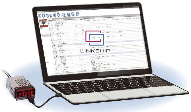
USB2.0 (Serial port communication via USB Virtual COM, 230.4kbps) |
| USB Communication Functions |
Write/read setting values / Continuous output of measured values |
| Output Update Time |
1ms - 9999ms, configurable in 1ms units
|
| General Specifications |
| Operating Temperature/Humidity Range |
-10°C to +50°C, 35 to 85%RH (Non-condensing) |
| Power Supply Voltage |
DC7-60V with reverse connection protection. Power supply from USB host: 5V |
| Power Consumption |
3W or less |
| Isolation |
Between Power supply / Current input / Other inputs & outputs |
| Weight |
Approx. 60g
|
| CAN Option |
| Communication Specs |
CAN2.0B 10k / 20k / 50k / 100k / 250k / 500k / 1M bps. Formats (INTEL/MOTOROLA), Frames (11bit/29bit) |
| Communication Functions |
Write/read setting values / Continuous output of measured values |
| Setting Items |
CAN Transmit ID, CAN Receive ID |
| Output Update Time |
1ms - 9999ms, configurable in 1ms units
|
| RS-485 Option Please consult us for Modbus RTU support as well |
| Connectable Units |
32 units (max) |
| Communication Format |
2-wire multi-drop serial communication |
| Communication Method |
Asynchronous |
| Communication Standard |
RS-485 |
| Communication Speed |
9600bps / 19200bps / 38400bps, set in program mode |
| Data Format |
Start bit: 1bit / Stop bit: 1bit / Data length: 8bit / Parity bit: None |
| Communication Code |
ASCII |
| Communication Functions |
Write/read setting values / Measured value output (responds to request commands)
|
| Analog Output Option |
| Output Signal |
[E1] 0 - 10V [E5] 0 - 5V [R1] ±10V [R5] ±5V [I1] 4 - 20mA 【Select Model】 |
| D/A Conversion Method |
DAC conversion method |
| Output Resolution |
16bit (over 50,000) |
| Load Resistance |
Voltage Output: 4.7kΩ or more | Current Output: 300Ω or less |
| Output Accuracy |
Voltage Output: ±0.1% of FS @ 23°C | Current Output: ±0.1% of FS @ 23°C |
| Temperature Fluctuation |
±200ppm/°C or less |
| Output Scaling |
Arbitrary scaling is possible via full-scale and zero-scale configurations |
| Output Update Time |
1ms - 9999ms, configurable in 1ms units
|
| Comparator (Alarm) Output Option |
| Setting Method |
Set in program mode |
| Number of Outputs |
2 points / 4 points (depending on model selection conditions) |
| Output Form |
Isolated solid-state output (PhotoMOS relay), non-polarized. When comparator operation condition is ON, resistance between COMP-COM is 50Ω or less |
| Output Load Voltage |
Peak AC/DC 280V 100mA (Resistive load), Max ON resistance 50Ω or less |
| Output Logic |
Comparison is performed with polarity (0 is greater than negative)
| [or more] |
ON when above or equal to the set value |
| [or less] |
ON when below or equal to the set value |
| [Within range] |
ON within the set range, OFF outside the range |
| [Outside range] |
ON outside the set range, OFF within the range |
|
| Update Time |
Based on the analog output update time setting. Response time 1ms (max) |