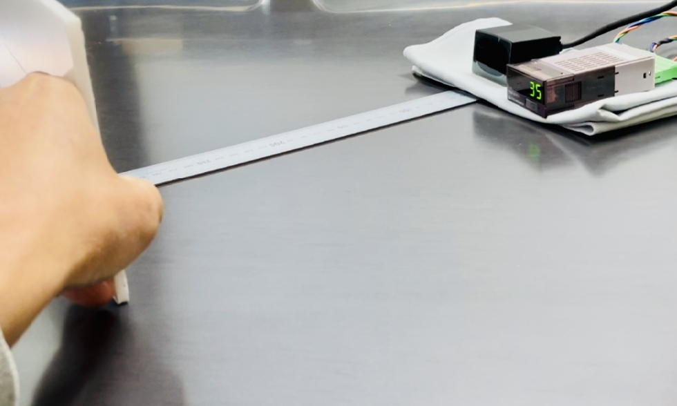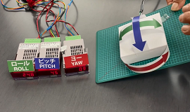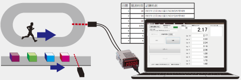
| No Complex Settings Required |
| No Expensive Analyzers Required |
| No Expensive Diagnostic Tools Required |
| View Analog Signal to CAN Converters > |
| CAN Input | |
| Receive data from messages on the CAN bus by specifying the CAN ID Automobiles, construction machinery, agricultural machinery, office equipment, etc.  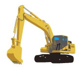
  |
 |
| Converter | ||||||||
|
|
|||||||
| 16-bit Analog Output | |
| Verify data with your own equipment Easily acquire CAN signals |
|
Logger |
Oscilloscope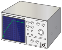 |
| CAN Input | |
| Specify the CAN ID to receive a specific CAN signal
|
|
| Converter | ||||||||
|
|
|||||||
| Alarm Output | |||
| Relay ON | External Power |
Voltage Applied |
Relay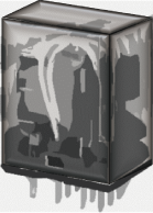 |
| PLC / Indicator Light, etc. |
  |
||
| View Application List > |
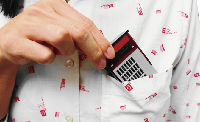
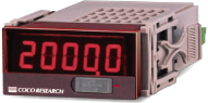
No expensive analyzers are required; you can easily start measuring from a single channel. When you want to increase the number of measurement channels, you can flexibly add more units later.
 |
 |
|
| > 1ms Output Update ver. |
| > Low-Cost 40ms Output Update ver. |
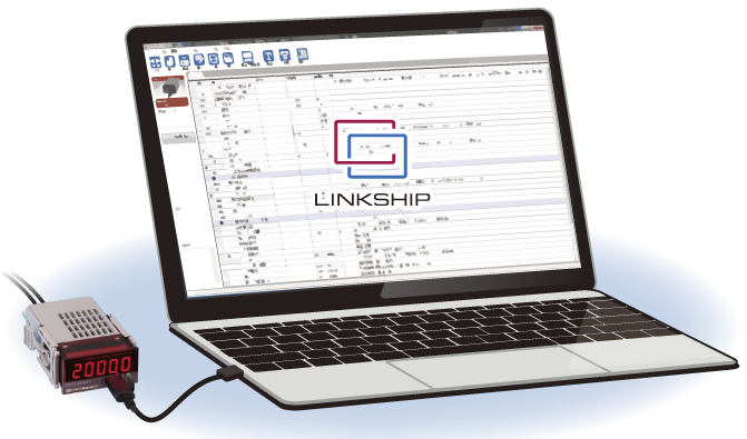
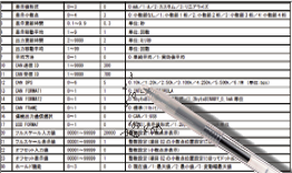
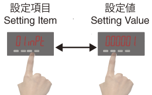
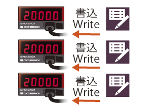
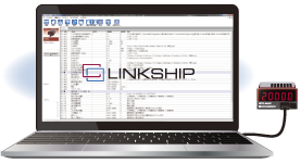
Unlike multi-functional machines, there are no deep menu hierarchies. Quickly configure settings via our dedicated free software.
 |
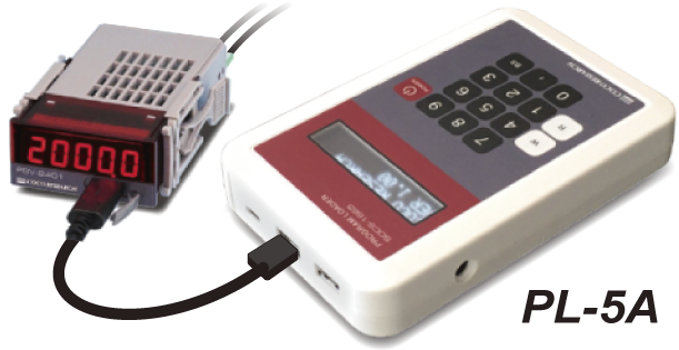 PC-free setting device (sold separately) |
| > View Configuration Software |
We can accommodate requests starting from a single unit for multi-channel/multi-type enclosures, as well as switch and connector installations (please contact us for details).
Example: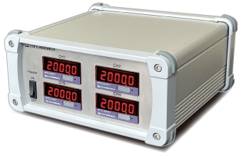
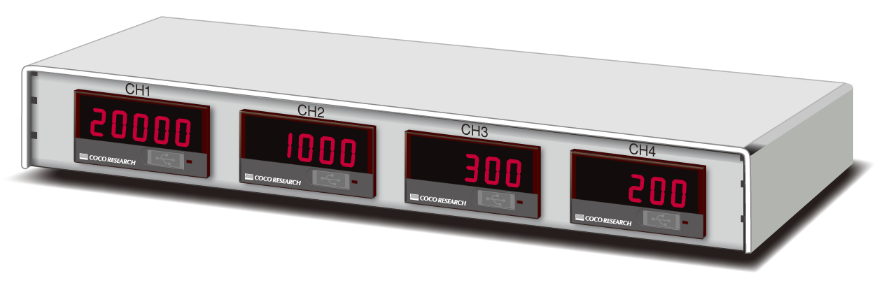
| > About Customization |
In addition to CAN to analog/alarm signal converters, we also offer various converters to CAN for speed, angle, torque, voltage, current, resistance, strain, temperature, flow rate, etc.
| Analog-CAN Converter | Various Meas. |
 |
CAN |
| CAN-Analog Converter | CAN |  |
Volt / Curr |
| > View Measurement Categories |
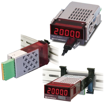
| > View Details |
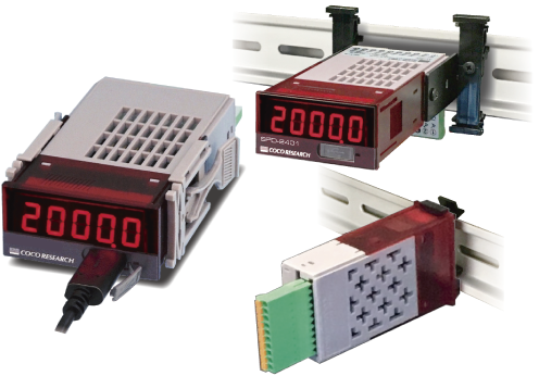
24x48mm Size
1CH Input
Upper 5-bit Mask Function
Loss Detection: CAN Bus Wiring Monitoring
Output
16-bit Analog (Voltage/Current)
Alarm
Output Update: from 1ms
Power Supply DC7 - 60V
24x48 DIN Size
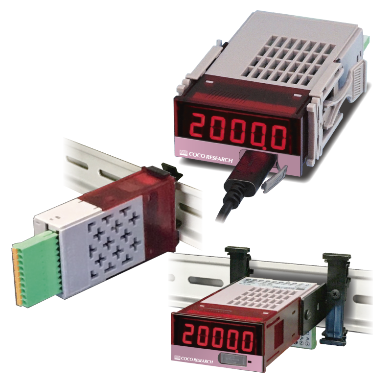
| > View Details |
24x48mm Size / Economy Model
1CH Input
Upper 5-bit Mask Function
Loss Detection: CAN Bus Wiring Monitoring
Output
16-bit Analog (Voltage/Current)
Alarm
Output Update: from 40ms
Power Supply DC7 - 30V
24x48 DIN Size
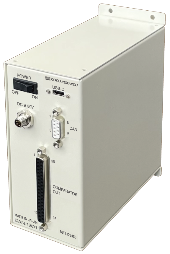
| > View Details |
CAN Input & 15CH Contact Output
15CH Input
Processes 15CH with a single CAN-ID
(When using 1-bit data)
Supports various received data types
15CH Contact Output
ON/OFF output based on comparison judgment
NPN Open Collector Signal
Output Update: Within 100ms
Power Supply DC9 - 30V
 With Case
| > View Details |
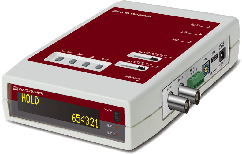
Handheld Type Active On-site
1CH Input
Output
16-bit Analog (Voltage/Current)
Alarm
Ethernet
Power Supply AA Batteries / AC Adapter
Selectable Connectors
BNC / M8 / Terminal Block, etc.
| > View Details |
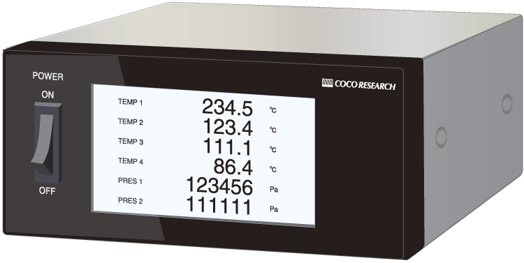
Lightweight & Ideal for In-vehicle Use
Multi-CH Input Customizable Item
Output
16-bit Analog (Voltage/Current)
Alarm
Ethernet / RS-485
HDMI (for Monitor Output)
Power Supply DC8-30V
Display Selectable (With / Without)
Selectable Connectors
BNC / LAN / D-sub / Terminal Block
| > View Details |
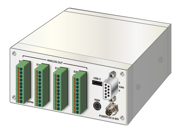
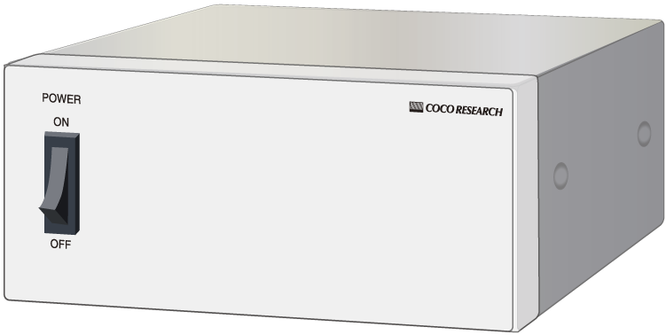
Flexible Layout for Channels, Connectors, etc.
Multi-CH Input Customizable Item
Output
16-bit Analog (Voltage/Current)
Alarm
Ethernet / RS-485
HDMI (for Monitor Output)
Power Supply DC8-30V
Selectable Connectors
BNC / LAN / D-sub / Terminal Block
| > View Details |
Calculates differences across 4 CAN inputs
Ideal for net flow rate calculation, etc.
4CH Input
Supports user-specified formulas (addition, subtraction, etc.)
Arbitrary scaling of output signals
Output
16-bit Analog (Voltage/Current)
Alarm
Output Update: from 40ms
*Faster updates available upon request
Power Supply DC7 - 30V
24x48 DIN Size
| > View Examples |
Reads data directly from the CAN bus by specifying the "CAN-ID", "Data Format", "Start Byte Position", etc. of the target parameter.
If you share your DBC file, we can pre-configure the settings before shipment free of charge.Received Data Format
- Single-precision Floating Point (32 bit)
- Double-precision Floating Point (64 bit)
- 16-bit Unsigned Integer (0 to 65535)
- 16-bit Signed Integer (-32,768 to +32,767)
- 32-bit Unsigned Integer (0 to 255)
- 32-bit Signed Integer (-2,147,483,648 to +2,147,483,647)
- 8-bit Unsigned Integer (0 to 15)
- 8-bit Signed Integer (-128 to +127)
- 1-bit Data Length (0 to 1)
BPS
10k, 20k, 50k, 100k, 250k, 500k, 1Mbps
FORMAT
- INTEL (Little Endian) /
- MOTOROLA (Big Endian)
FRAME
- Standard (11-bit ID) /
- Extended (29-bit ID)
Upper 5-bit Mask Function
[CAN/CANL-24*1 Only]
When using Extended (29-bit) IDs, reception judgment can be performed while ignoring the upper 5 bits.
| Priority | EDP | Data page | PDU format | PDU specific | Source address |
3 bits |
1 bit |
1 bit |
8 bits |
8 bits |
8 bits |
| Mask (Upper 5 bits) | Detect here | ||||
Loss Detection Function (CAN Bus Line Monitoring)
[CAN/CANL-24*1 Only]
Displays "OFF" when CAN bus data reception stops.
Analog output* or alarm output options are also available.
Detection time threshold can be configured from 1 to 999s.
*Analog output during loss can be selected from: 0, +Max, or -Max.
Reception Loss |
|
OFF Display |
Analog / Alarm Output |
| 0-10V | 0-5V | 4-20mA |
| ±10V | ±5V | Select on order |
Resolution over 50,000, Full/Zero scale settings, Analog output zero adjustment
| 2 pts | 4 pts |
| Configuration | Data Logging | Bus Power |
[Logging and bus power functions are available for CAN/CANL-24 only]
| > Go to LINKSHIP Page |

Pluggable Terminal Blocks
Easy attach/detach after wiring
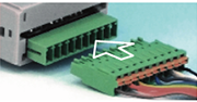
Pluggable Connectors
Spring-lock type
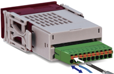
Pluggable Connectors
M2 screw clamp type
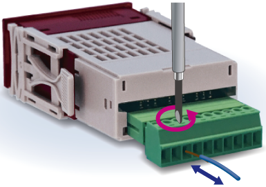
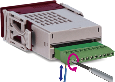
Fixed Connectors also available
[Custom Support]
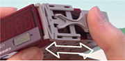
Smooth unit attachment
Mounting hooks (Left/Right)
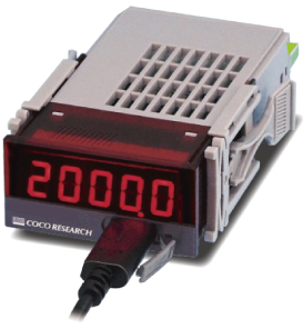
Carry your PC/tablet, device, and cables to measure anywhere via USB bus power. Sturdy storage case BXS-1 (sold separately) is available.
|
 > BXS-1 Overview |
Ultra-compact 24x48mm size contributes to substantial space saving.
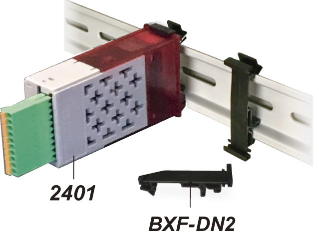
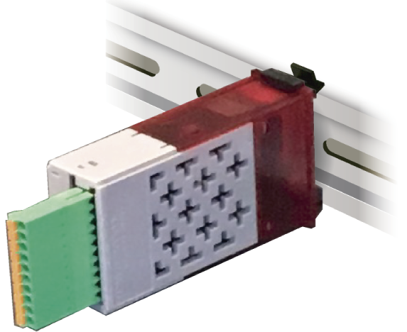
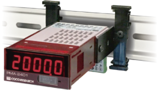
One-touch mounting adapters and displayless models are available.
 |
 |
 |
| BXF-DN2 DIN Rail Adapter (Sold Separately) |
CAN-2451 Without Display |
CAN-2431 With Display |
| > Go to BXF-DN2 Page | > View Description for 2451 & 2431 | |
| Product Name | CAN-to-Analog Converter | ||||||||
| Model Name | CAN-2401 / CAN-2411 / CAN-2431 / CAN-2451 |
||||||||
| Input Section | |||||||||
| Number of Inputs | 1 point | ||||||||
| Communication Standard | CAN 2.0B | ||||||||
| CAN Baud Rate (BPS) | Selectable from 10k / 20k / 50k / 100k / 250k / 500k / 1M bps | ||||||||
| CAN Format | Selectable from INTEL (Little Endian) / MOTOROLA (Big Endian) | ||||||||
| CAN Frame | Selectable from Standard (11-bit ID) / Extended (29-bit ID) | ||||||||
| Extended ID Upper 5-bit Mask | Upper 5-bit masking for 29-bit Extended IDs: Allows validation while filtering out priority/EDP bits | ||||||||
| Received Data Format | Selectable from FLOAT, DOUBLE, U32, S32, U16, S16, U8, S8, 1-bit | ||||||||
| Data Frame | 8 Bytes (Configurable data format and read start byte position) | ||||||||
| Bit-level Extraction | Extracts 1-bit data from a bit array numbered 0 to 63 bits (Specifies byte and bit offset) | ||||||||
| Data Loss Detection | Triggers when CAN reception ceases. Time threshold configurable from 1s to 999s. Loss event can be assigned to the COM1 alarm output terminal (triggers after threshold timeout). |
||||||||
| Input Connector | Spring-lock pluggable connector / Optional: M2 screw pluggable connector |
||||||||
| Processing Section | |||||||||
| Measurement Mode | Selectable from Raw CAN Integer Data / 2-Point Linear Calibration scaling | ||||||||
| Memory Backup | Non-volatile memory (EEPROM) |
||||||||
| Display Section | |||||||||
| Main Numeric Display | 5-digit 7-segment LED, Character height: 9mm. CAN-24: Red LED / CAN-24-G: Green LED (Option) Display Range: -19999 to 99999 Overflow Indicator: "OL" | Zero Blanking: Leading zero suppression Display Refresh Rate: 0.3s (Configurable within 0.1s to 9.9s range) | Accuracy: 20ppm ±1 digit at 23℃ |
||||||||
| Decimal Point Position | Configurable via Program Mode (0: □□□□□ to 4: □.□□□□) | ||||||||
| Status Indicators | 1x LED for Power Status |
||||||||
| USB Interface | |||||||||
| USB Specs | USB 2.0 (Serial communication via Virtual COM Port, 230.4kbps) | ||||||||
| USB Functions | Read/Write configurations, Continuous live measurement output | ||||||||
| Output Refresh Interval | 1ms to 9999ms (Configurable in steps of 1ms) |
||||||||
| General Specifications | |||||||||
| Operating Environment | -10℃ to +50℃, 35 to 85% RH (Non-condensing) | ||||||||
| Supply Voltage | DC7-60V (With reverse polarity protection). Power from USB host: 5V | ||||||||
| Power Consumption | 3W or less | ||||||||
| Isolation | Between power supply line and all other inputs/outputs | ||||||||
| Dielectric Strength | Between power supply line and all other I/O: DC500V for 1 minute | ||||||||
| Net Weight | Approx. 60g |
||||||||
| Analog Output Option | |||||||||
| Output Signals | [E1] 0 - 10V [E5] 0 - 5V [R1] ±10V [R5] ±5V [I1] 4 - 20mA 【Selectable Model】 | ||||||||
| D/A Method | DAC system | ||||||||
| Output Resolution | 16-bit (Equivalent to 50,000 divisions or higher) | ||||||||
| Load Resistance | Voltage Output: 4.7kΩ or more | Current Output: 300Ω or less | ||||||||
| Output Accuracy | Voltage Output: ±0.1% of FS @23℃ | Current Output: ±0.1% of FS @23℃ | ||||||||
| Temperature Coefficient | ±200ppm/℃ or less | ||||||||
| Output Scaling | Flexible mapping through Full-scale and Zero-scale settings | ||||||||
| Output Update Interval | 1ms to 9999ms (Configurable in steps of 1ms) | ||||||||
| I/O Response Delay | Output update setting time + Analog rise time (150μs max) |
||||||||
| Comparator (Alarm) Output Option | |||||||||
| Configuration Method | Set via Program Mode | ||||||||
| Number of Outputs | 2 points / 4 points (Depending on the selected model code) | ||||||||
| Output Structure | Isolated Solid-State Relay (PhotoMOS Relay), Non-polar. On-resistance between COMP-COM is 50Ω or less under active state. | ||||||||
| Max Load Capacity | Peak AC/DC 280V, 100mA (Resistive load) | Max ON-resistance: 50Ω | ||||||||
| Output Logic | Comparison handles positive/negative signs (e.g., 0 is evaluated as greater than negative values)
|
||||||||
| Response Time | Tied to the Analog output update cycle. Ultimate response: 1ms (max) | ||||||||
Consolidate massive wiring bundles into a single CAN bus line to minimize complexity.
Easily map retrofitted analog sensors directly into your CAN framework.
| View Product List > |
| Load Cell / Pressure / Strain | DC Current | DC Voltage |
| Thermocouple (Temp) | Thermistor (Temp) | RTD (Temp) |
| Speed / Totalization | Frequency Deviation / Torque | Resistance |
- CAN and 16-bit Analog (Voltage/Current) simultaneous output
- USB-C: Easy configuration and data logging interface
- Alarm output / RS-485 communication options
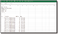
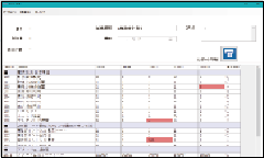
- Free dedicated utility software: Parameter management, report layout printing, and data logging
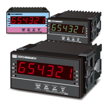
EX48
EX(L)24