2 Flow Meters, 2 Thermocouples, 1 Elapsed Time Timer / Wired Remote Controller Included / Various Output Options
- Measures flow rate, temperature, and elapsed time to collect data for flow rate compensation.
- Measures feed and return flow rates and temperatures to calculate net flow/consumption, or monitors mixing conditions of Liquid A and Liquid B.
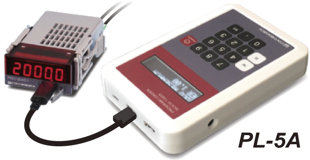
- Start, stop, and reset flow rate and time measurements simultaneously using the handheld wired remote controller.
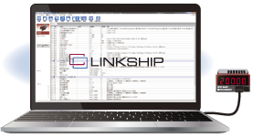
- Easily perform data logging and CSV export using the instrument with the LINKSHIP Measurement Management Software.
| View Application Details > |
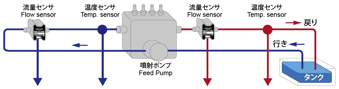
| Inlet Flow Rate Frequency Pulse Signal |
Inlet Temperature Thermocouple Signal |
Outlet Flow Rate Frequency Pulse Signal |
Outlet Temperature Thermocouple Signal |
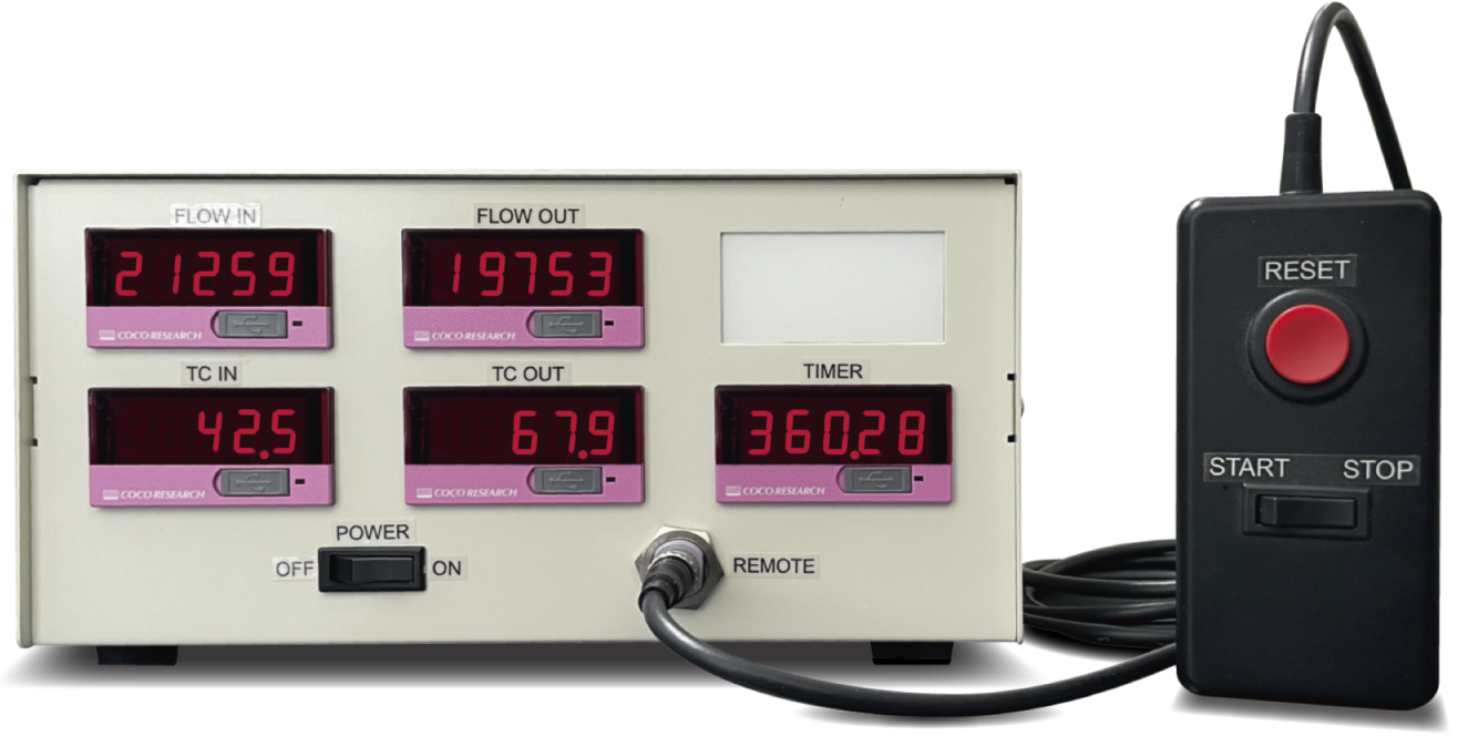
|
|
|
|
|
*Display update is not synchronized |
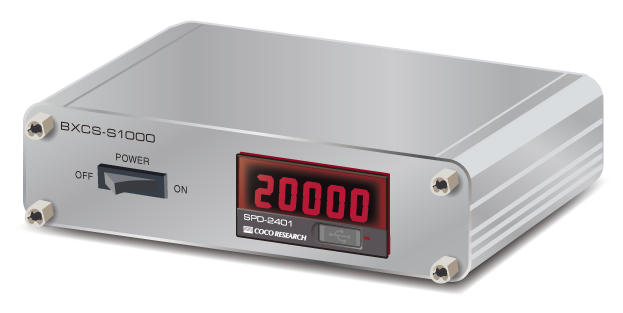
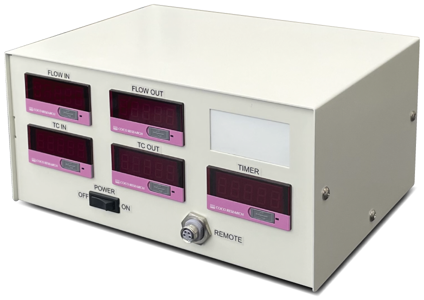 ▲ Main Unit Dimensions: W200 x H95 x D150 mm (excluding projections)
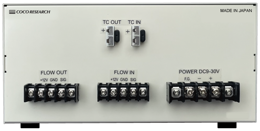 ▲ Rear View Example: Without Output Options
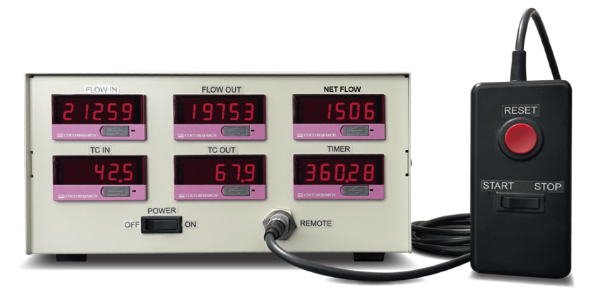 ▲ Total Flow Difference Indicator (Inlet Flow - Outlet Flow) Model Also Available
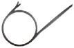
Temp. Measurement: Thermocouple Input Type
 Product Page HTL-2401
Supports 8 types of thermocouples (K, J, R, E, T, B, N, S) via setting configuration
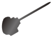

Temp. Measurement: RTD Input Type
Product Page HTL-2401R
Supports RTD Pt100 (3-wire)
Resistance Check Function Included
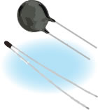
Temp. Measurement: NTC Thermistor Input Type
Product Page HTL-2401T
Supports NTC Thermistors
High Conversion Accuracy with Proprietary Algorithm
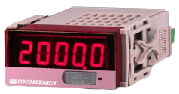
Flow Rate (Total) / Flow Velocity (Instantaneous) Meter [Switchable]
Product Page SPDL-2401
Supports Flow Sensors with Frequency Pulse Output
Measures Flow Rate and Velocity via Setting Configuration
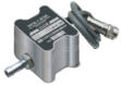

| 5V Logic |
| Zero-Cross |
| NPN Open Collector |
| 12V Logic |
| Custom Signals |
| Isolated Input |
| Phase A/B Input |
| Line Driver |
| Trigger Level 0-9.00V |
| Hysteresis: 3 Steps |
| Pull-up ON/OFF |
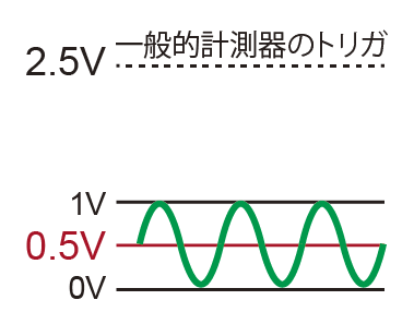
While standard instruments are fixed at 2.5V, SPD allows settings from 0 to 9V in 10mV increments, supporting a wide range of sensors.
| Threshold 0.5V | Threshold 7V | ||
 |
or | 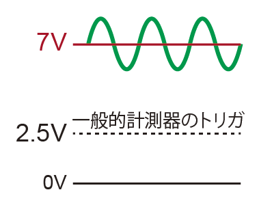 |
can be connected |
| 5V |
| 12V |
| Other Voltages |
|
| Resolution: 50,000 counts or higher |
| Full-scale / Zero-scale setting |
| Analog output zero adjustment |
Dual analog outputs also available
| High (At or above set value) |
| Low (At or below set value) |
| Out of Range |
| In Range |
| Data Logging |
| Configuration |
| Go to LINKSHIP Page > |
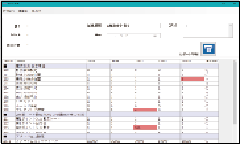
CSV Logging
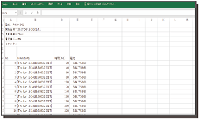
Compare & Verify Settings
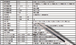
Save & Copy Settings to PC
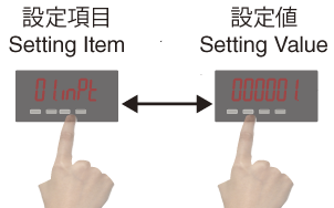
Prevent Operational & Setting Errors
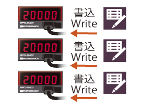
Reduce Setup Man-Hours
| Product Name | Fuel Consumption Indicator | |
| Input Section | ||
| Thermocouple Input | Miniature Connector 2 Channels | |
| Single-Phase Signal Input | Terminal Block 2 Channels (with +12V 60mA Power Supply Terminal for Sensor) | |
| Totalized Flow Rate (Single-Phase Pulse Signal Input) Measurement Function | ||
| Upper Frequency Limit | 1MHz | |
| Withstand Voltage | ±30V | |
| Low-Pass Filter | OFF / 500Hz / 5kHz / 120kHz / 800kHz [Configurable in Program Mode] | |
| Sensor Power Supply | 12V DC ±10% 60mA | |
| Thermocouple Measurement Function | ||
| Thermocouple Type | K, J, R, E, T, B, N, S [Configurable in Program Mode] | |
| Measurement Range | Range A (0.1°C): -240.0 to 400.0°C / Range B (1°C): -270.0 to 400.0°C | |
| Accuracy (±0.5% FS) * Accuracy in parentheses is specified at an output update setting of 100 ms * Within the measurement range, measurement is available with a resolution of 0.1°C |
||
| Cold Junction Compensation Error | ±2°C | |
| Measurement Resolution | Range A: 0.1°C / Range B: 1°C | |
| Arithmetic Section | ||
| Setting Value Memory | Non-volatile memory (EEPROM) Stored per instrument | |
| Totalized Flow Meter | ||
| Measurement Mode | Measurement and display of totalized flow rate (Unit can be set to any arbitrary unit such as L or mL) Start/Stop flow measurement using the Start/Stop switch on the remote controller Zero reset using the Reset button |
|
| Totalizing Rate | Set the amount of change per input pulse | |
| Thermocouple Meter | ||
| Measurement Mode | Unit: Celsius °C (Unit can also be changed to Fahrenheit) | |
| Timer | ||
| Measurement Mode | Measurement and display of elapsed time (Unit can be set to any arbitrary unit such as seconds or milliseconds) Start/Stop elapsed time measurement using the Start/Stop switch on the remote controller Zero reset using the Reset button |
|
| Display Section | ||
| Display | 7-segment 5 digits, Character height 9mm, Red, Turn-off capability | |
| Display Update Interval | 0.1 sec (Settable in the range of 0.1 to 9.9 sec) | |
| Moving Average Display | 1 (Settable in the range of 1 to 9) * Applicable only to thermocouple measurement | |
| Display Range | -19999 to 99999 / Overrange display: OL / Zero display: Leading zero suppression | |
| Decimal Point Position | For Inlet Flow Meter, Outlet Flow Meter, and Timer: 0: □□□□□ (No decimal point) / 1: □□□□.□ to 4: □.□□□□ * Configurable in Program Mode For Inlet Thermocouple Meter and Outlet Thermocouple Meter: □□□□.□ (Fixed 1 decimal digit) |
|
| USB Communication Section | ||
| Communication Specifications | USB 2.0 (Serial port communication via USB Virtual COM, 230.4 kbps) | |
| Communication Function | Read/Write setting values / Continuous output of measured values | |
| Output Update Interval | 40ms - 9999.9ms (Settable in 0.1ms steps) | |
| General Specifications | ||
| Isolation | Inlet Flow Sensor Input / Outlet Flow Sensor Input / Inlet Thermocouple Input / Outlet Thermocouple Input / Main Power Supply Input / Enclosure |
|
| External Dimensions | Main unit: W200 x H95 x D150 mm / Remote controller: W45 x H90 x H25 mm, Cable length: 1.5 m * Excluding projections such as connectors and feet |
|
| Power Supply Voltage | 9 to 30V DC | |
| Operating Temperature Range | 0 to 40 °C / 85% RH or less (Non-condensing) | |
| CAN Option | |||||||||
| Communication Specifications | CAN 2.0B: 10k / 20k / 50k / 100k / 250k / 500k / 1M bps [Configurable in Program Mode] Format: INTEL / MOTOROLA Frame: 11-bit / 29-bit |
||||||||
| Communication Function | Read/Write setting values / Continuous output of measured values | ||||||||
| Setting Items | CAN TX ID, CAN RX ID | ||||||||
| Output Update Interval | 40ms - 9999ms (Settable in 2ms steps) |
||||||||
| RS-485 Option Modbus RTU support is also available upon request | |||||||||
| Max. Connected Units | 32 units (Max.) | ||||||||
| Communication Topology | 2-wire multi-drop serial communication | ||||||||
| Communication Method | Asynchronous method | ||||||||
| Communication Standard | RS-485 | ||||||||
| Baud Rate | 9600bps / 19200bps / 38400bps [Configurable in Program Mode] | ||||||||
| Data Format | Start bit: 1 bit / Stop bit: 1 bit / Data length: 8 bits / Parity bit: None | ||||||||
| Communication Code | ASCII | ||||||||
| Communication Function | Read/Write setting values / Output measured values (Responds to request commands) |
||||||||
| Analog Output Option | |||||||||
| Output Signal | [E1] 0-10V [E5] 0-5V [R1] ±10V [R5] ±5V [I1] 4-20mA [Select model] | ||||||||
| D/A Conversion Method | DAC conversion method | ||||||||
| Output Resolution | 16-bit (50,000 counts or more) | ||||||||
| Load Resistance | Voltage output: 4.7 kΩ or higher Current output: 300 Ω or lower | ||||||||
| Output Accuracy | Voltage output: ±0.1% of FS @ 23°C Current output: ±0.1% of FS @ 23°C | ||||||||
| Temperature Drift | ±200 ppm/°C or less | ||||||||
| Output Scaling | Arbitrary scaling is possible by setting full-scale and zero-scale values | ||||||||
| Output Update Interval | 40ms - 9999ms (Settable in 2ms steps) | ||||||||
| Output Response Time | 1 ms or less (0 → 90% response) |
||||||||
| Comparator (Alarm/Alert) Output Option | |||||||||
| Setting Method | Set in Program Mode | ||||||||
| Number of Outputs | 2 points / 4 points (Depending on model selection conditions) | ||||||||
| Output Type | Isolated solid-state output (PhotoMOS relay), non-polar When comparator condition is ON, resistance between COMP-COM is 50 Ω or less |
||||||||
| Output Load Voltage | Peak AC/DC 280V 100mA (Resistive load), ON resistance Max. 50 Ω or less | ||||||||
| Output Logic | Comparison is performed with polarity (0 is greater than negative values)
|
||||||||
| Update Interval | Depends on analog output update interval setting / Response time: 1 ms (Max.) | ||||||||
- CAN Output
- 16-bit Analog (Voltage/Current) Output / Dual Outputs
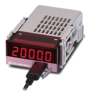
- USB-C: Configuration & Data Logging
- Alarm Output / RS-485
- Free Setup & Management Software: Report Printing & Data Logging
- Ethernet (LAN) [EX48]
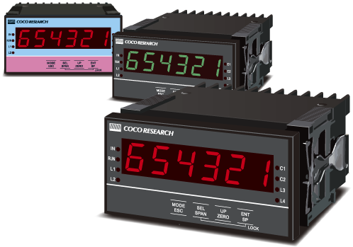
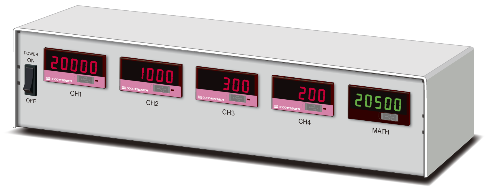
・Custom calculation formulas (addition, subtraction, averaging, etc.) can be specified (Please contact us)
・Arbitrary scaling of input/output values is possible
・Simultaneous display of each channel input value and calculated value
・Custom print labels (e.g., CH1-4 or MATH designations) can also be specified
| View Product Page > |
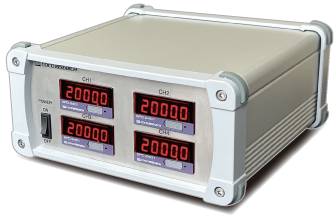
Specification Example
Flow Sensor 1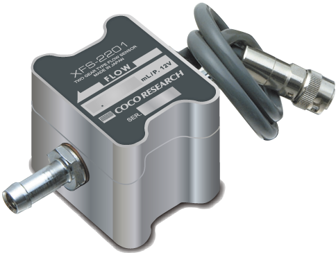 |
Flow Sensor 2 |
Flow Sensor 3 |
Flow Sensor 4 |
|||||
|
|
|
|
|||||
 |
|
|
|
 |
|
 Display / Analog Output
|
| View More > |
| View More > |
| View More > |
| View More > |
| View More > |
| View More > |
 |
 |
 |
 |
||||
|
|
|
|
||||
 |
 |
 |
 |
||||
|
|
|
|
||||
LCD Monitor |
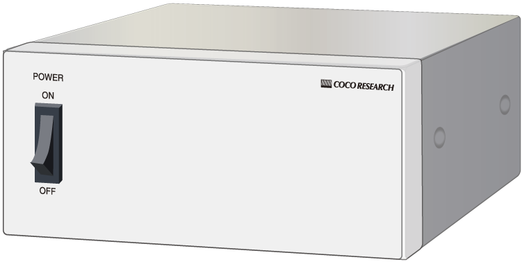 Without Display |
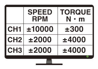 External Monitor Output Free monitor display software*Monitor not included |
| AC |
| DC |
 |
 |
 |
 |